Assigning and working with enforced motion loads
Any referenced datasets can be downloaded from "Module downloads" in the module overview.
Enforced motion loads - Exercise
- Open the Enforced Motion.ipt part from your working folder.
- In the Environments tab>Begin panel, click Autodesk Inventor Nastran.
- In the Setup panel, click Loads.
- In the Load dialog box, do the following:
- Change the name to 1/8” Displacement.
- Change the Type to Enforced Motion.
- The Sub Type should be Displacement.
- Click the edge shown in the image below (edge<8>) for Selected Entities.
- Input 0.125 for Tz.
- Check the box next to the glasses at the bottom.
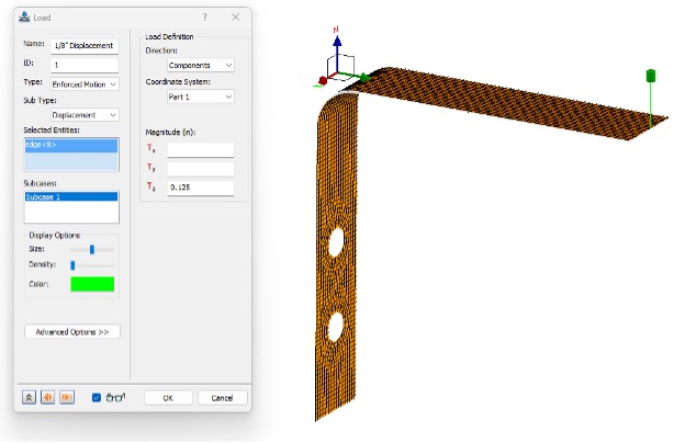
- Review the inputs and click OK.
- In the Setup panel, click Constraints.
- In the Constraint dialog box, do the following:
- Change the name to EM Constraint.
- Choose the same edge as the enforced motion load (edge<8>) for Selected Entities.
- Clear all the Degrees of Freedom checkboxes, except for Tz.
- Check the box next to the glasses at the bottom.
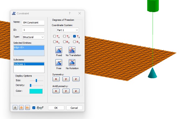
- Review the inputs and click OK.
- In the Setup panel, click Constraints.
- In the Constraint dialog box, do the following:
- Change the name to Hole 1.
- Select the edge shown below (edge<1>) for Selected Entities.
- Check the box next to the glasses at the bottom.
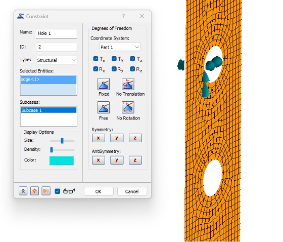
- Select OK.
- In the Setup panel, click Constraints.
- In the Constraint dialog box, do the following:
- Change the name to Hole 2.
- Select the edge shown below (edge<6>) for Selected Entities.
- Check the box next to the glasses at the bottom.
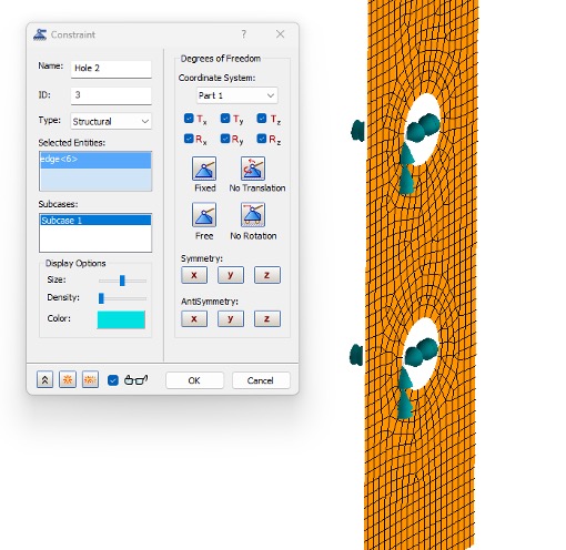
- Select OK.
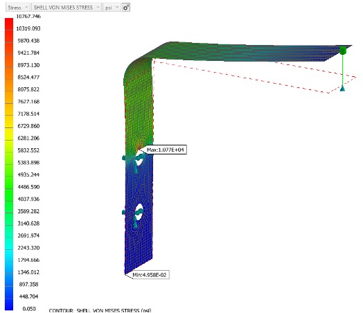
- On the Solve panel, select Run.
- Review the results for Stress and Displacement.
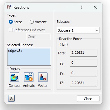
- Under Constraints in the Analysis Tree, right-click on EM Constraint and select Reactions.
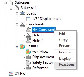
- Review the reaction forces.
- Select Close when finished.
- Save and Close the model.