Assigning contacts in a Nastran analysis
Any referenced datasets can be downloaded from "Module downloads" in the module overview.
Assign contacts in a Nastran analysis – Exercise
- Open the Yoke Asm QTR.iam file from your working folder.
- In the Environments tab>Begin panel, click Autodesk Inventor Nastran.
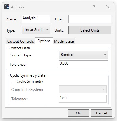
- In the Nastran Model Tree, double-click on Analysis 1.
- In the Analysis dialog box, select the Options tab. Confirm that the default Contact Type is set to Bonded and click OK.
- Change the Tolerance value to 0.005.
- In the Setup panel, click Constraints.
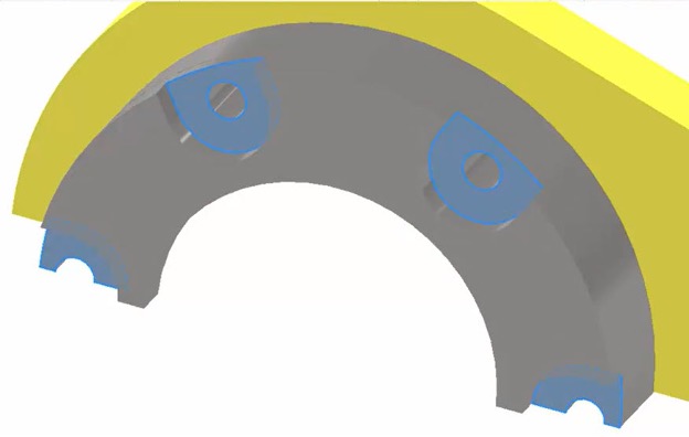
- With the Constraint dialog box open, select the eight surfaces where the bolts would touch, as shown below.
- In the Constraint dialog box, change the Name to Fixed and click OK.
- Rotate the model so you can view the symmetry plane. In the Setup panel, click Constraints again.
- In the Constraints dialog box, change the Name to Y symm.
- In the Symmetry section, click y.
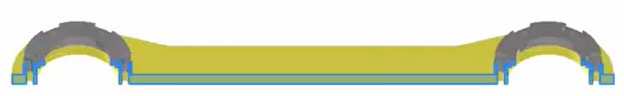
- In the graphics window, select all the surfaces on the cut plane, as shown below.
- Click OK.
- Rotate the model around to view the back face. In the Setup panel, click Constraints again.
- In the Constraints dialog box, change the Name to Z symm.
- In the Symmetry section, click z.
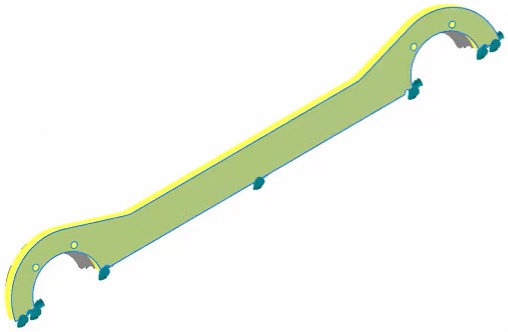
- In the graphics window, select the surface that lies on that plane, as shown below.
- Click OK.
- In the Setup panel, click Loads.
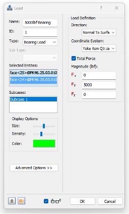
- Change the Name to 5000lbf Bearing.
- Change the Type to Bearing Load.
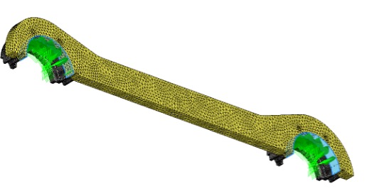
- With the Load dialog box open, select the inside of the yoke's holes, as shown below.
- Check the box for Total Force.
- In the Load dialog box, in the Magnitude (lbf) section, set Fx to 5000 and click OK.
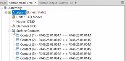
- In the Contacts panel, click Auto. The contacts will be automatically generated and added to the model tree.
- In the Nastran Model Tree, expand the Surface Contacts node and note the different contact pairs that have been added.
- In the Solve panel, click Run to run the analysis. When the Nastran Solution Complete message displays, click OK.
- From the Results panel, click Deformed to turn off the exaggerated deformation.
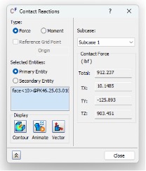
- Under Surface Contacts in the Analysis tree, right-click on "Contact (1) - PK46.25.01.004:1 <-> PK46.25.01.014:1" and select Contact Reactions.
NOTE: Contact pair reactions is a new feature in the 2024 version of Inventor Nastran. If using an earlier version, please proceed to step 32. - View the contact reaction forces and notice that this contact set is creating a 125lbf force in the Y direction.
- Click Close.
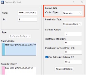
- Under Surface Contacts in the Analysis tree, right-click on "Contact (1) - PK46.25.01.004:1 <-> PK46.25.01.014:1" and select Edit.
- Change the Contact Type to Separation using the drop-down menu.
- Click OK.
- Repeat steps 28-29 for "Contact (2) - PK46.25.01.004:2 <-> PK46.25.01.014:2."
- From the Solve panel, select Run. (Note: this study will take longer than the prior.)
- Click OK once the analysis solves successfully.
- View the new Von Mises Stress, Displacement, and Contact Reaction results.
- Save and close the model.