Modeling cable tray horizontally
Any referenced datasets can be downloaded from "Module downloads" in the module overview.
Model a cable tray horizontally on a wall in Revit - Exercise
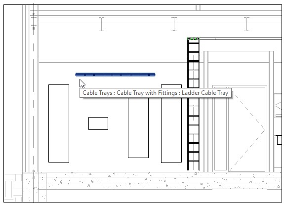
- Open the Small Medical Center-Cable Tray Horizontal.rvt project. You are in the Electrical Room South Wall section view, facing the panels. You can see the vertical cable tray that was added in the previous practice.
- Start the Cable Tray command and draw a cable tray horizontally. Width is always seen as the value visible in plan and height in elevation.
- Delete the horizontal cable tray.
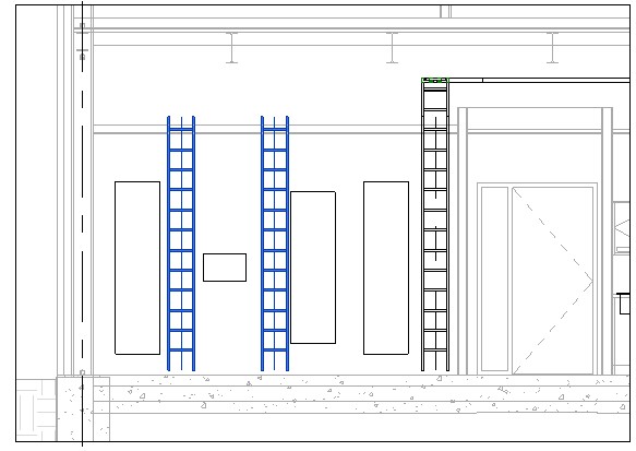
- Copy the vertical cable tray twice, as shown below.
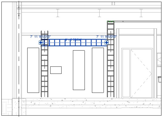
- Rotate the middle cable tray 90° and drag it into position above the electrical panels, as shown below. (Do not use controls.)
- Nudge the vertical cable tray along the right wall over closer to the walls. This is done by selecting the element and using the arrow keys on the keyboard.
- Many standard commands that work fine in plan do not work on the horizontal cable tray. For example, if you try to use the connectors, by dragging the control from the horizontal cable tray to the vertical cable tray. It rotates it back to the way the program wants it to be and there is an additional error.
- Click Undo.
- Select the horizontal cable tray and change the length using the temporary dimension to 6'-0".
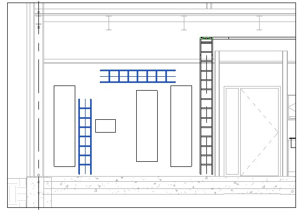
- The vertical cable tray can be modified using the control. Drag it down some so the model looks similar to the example below.
- In the Systems tab > Electrical panel, click Cable Tray Fitting.
- In the Type Selector, select Ladder Horizontal Bend: Standard.
- Hover over the left end of the horizontal tray. It can be placed here but it will not go in the direction needed, as shown below.
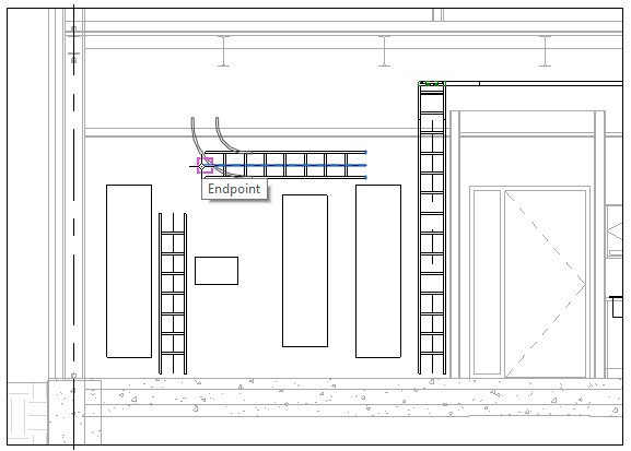
- Hover over the top of the vertical cable tray and it looks like it is going to be placed as expected, as shown below.
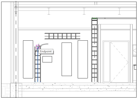
- Click to place the fitting and it places it at the other end facing the wrong direction, as shown below.
- Delete the fitting.
- Start the Cable Tray Fitting command again and place the fitting in the view where it isn't touching anything.
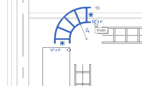
- Use the rotate controls on the fitting to rotate it around until you see the ladder side, as shown below.
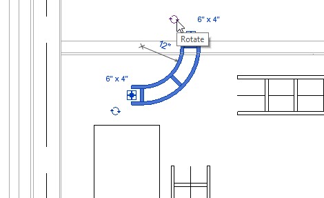
- Use the Rotate command to rotate it to the correct direction.
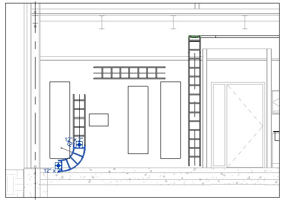
- Use the Width control and set the Width to 12", as shown below.
- Drag the fitting in to place but do not use connectors.
- Nudge the elements into place using the keyboard arrows.
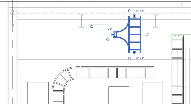
- In the Systems tab> Electrical panel click Cable Tray Fitting.
- In the Type Selector, select Ladder Horizontal Tee: 12" Radius.
- Place the fitting away from the cable tray and use the rotate controls and the Rotate command to get it facing the right way. Make sure you see the ladder.
- Change the Width controls to 12", as shown below.
- Drag the fitting to the correct location over the vertical cable tray and in alignment with the horizontal cable tray, as shown below.
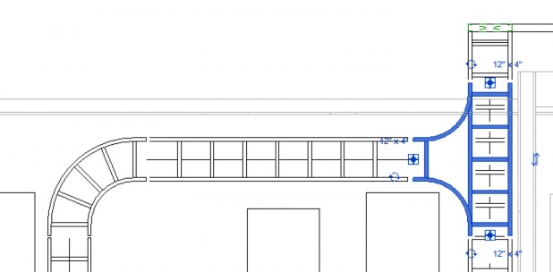
- In the Modify tab > Modify panel, click Split.
- Click two points along the vertical cable tray. If a warning displays, click Delete Elements. Make sure the split cable tray is removed.
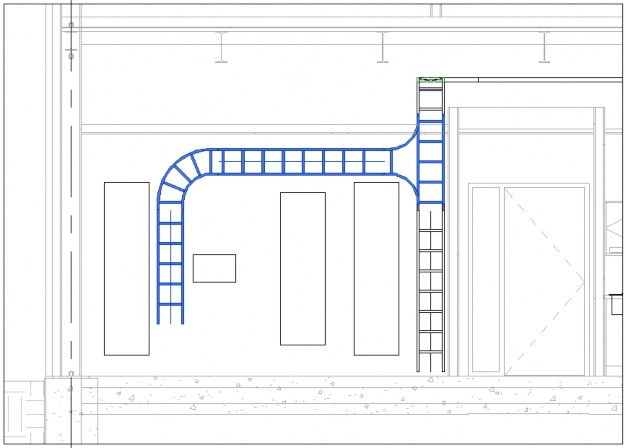
- You can now nudge the individual cable trays and fittings into place and change the length using temporary dimensions.
- By adding in cable tray that rests against a wall, you can have an accurate takeoff of cable tray and fittings in your schedules.
- Save the project.