| |
| |
Completion Time: 25 Minutes
|
Completion of Lesson Circuits
| |
Objective: In this exercise, you use AutoCAD® Electrical commands to manipulate circuits. You copy an existing circuit, save a circuit to the Saved User Circuits icon menu, and insert the saved circuit you created.
|
| |
Process: Completion of the Circuits Lesson
|
| |
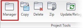
1: If the Project Manager is not displayed, on the Project tab, Project Tools panel, click Manager.
|
| |
2: If Schematic_Components_NFPA is the active project, skip to step 6. If it is open but not active in the Project Manager, do the following:
> Right-click Schematic_Components_NFPA
> Click Activate.
> Skip to step 6.
|
| |
3: In the Project Manager, click Open Project.
|
| |
4: Browse to where you installed the exercise files. Select Schematic_Components_NFPA.wdp. Click Open.
|
| |
5: In the Projects list, click the expansion node next to Schematic_Components_NFPA to expand the drawing list in the manager.
|
| |
6: Right-click Schematic_Components_NFPA_03.dwg. Click Open.
|
| |
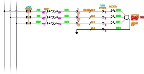
7: Zoom in to rungs 307-314 of the first ladder.
|
| |
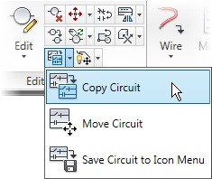
8: On the Schematic tab, Edit Components panel, Copy Circuit flyout, click Copy Circuit.
|
| |
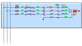
9: Select all objects that make up the circuit on rungs 308-310. Press ENTER.
|
| |
10: Click the base point as the endpoint of rung 308 on the left vertical bus.
Note: Be sure to use the Snap or an Osnap command to ensure that you are on the endpoint.
|
| |
11: Click the second point of displacement at rung 311 on the left vertical bus. In the Copy Circuit Options dialog box, click OK to accept the defaults.
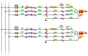
Notice how the component tags are updated to match the inserted locations.
|
| |
12: Save Circuit to Menu:
On the Quick Access toolbar, click Previous Drawing.

This opens the previous drawing in the Projects list, Schematic_Wiring_NFPA_02.dwg.
|
| |
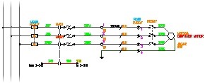
13: Zoom in to rungs 206-210.
|
| |
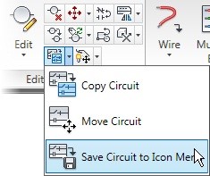
14: On the Schematic tab, Edit Components panel, Copy Circuit flyout, click Save Circuit to Icon Menu.
|
| |
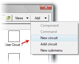
15: In the Save Circuit to Icon Menu dialog box, click Add, New Circuit.
|
| |
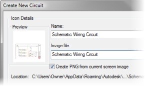
16: For Name, enter "Schematic Wiring Circuit"
|
| |
17: For Image File, enter "Schematic Wiring Circuit"
|
| |
18: Click Create PNG from Current Screen Image.
|
| |
19: Click Zoom. In the drawing, make the image of the circuit as large as possible.
Exit the Real-time Zoom command to return to the Create New Circuit dialog box.
|
| |
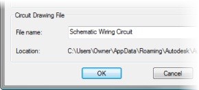
20: For File Name, enter "Schematic Wiring Circuit". Click OK.
|
| |
21: Click the endpoint of rung 207 on the left vertical bus. This is the base point.
Note: Use the Snap or an Osnap command to ensure that you click the endpoint.
|
| |
22: Select all objects that make up the circuit on rungs 207-209. Press ENTER.

An icon for the saved circuit is added to the menu.
|
| |
23: Click OK to close the menu
|
| |
24: Insert Circuit from Menu
On the Quick Access toolbar, click Next Drawing.

This opens Schematic_Wiring_NFPA_03.dwg.
|
| |
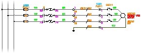
25: On the Schematic_Wiring_NFPA_03.dwg drawing, zoom in to rungs 310-316.
|
| |
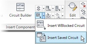
26: On the Schematic tab, Insert Components panel, Insert WBlocked Circuit flyout, click Insert Saved Circuit.
|
| |
27: Click Schematic Wiring Circuit.

|
| |
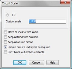
28: In the Circuit Scale dialog box, accept the default options. Click OK.
|
| |
29: Select the insertion point at rung 314 on the left vertical bus.

The circuit is inserted and component tags are updated.
|
|