| |
| |
Completion Time: 45 Minutes
|
Completion of the Using the Terminal Strip Editor Lesson
| |
Objective: In this exercise, you extract the terminal information from your project drawings into a panel layout drawing.
You complete the following steps:
■ Insert a DIN rail for mounting the terminal strip.
■ Extract a terminal strip, sorting the terminals and editing the wire destinations.
■ Add spare terminals and accessories including catalog information.
■ Insert the terminal strip in a panel drawing using a graphical representation.
■ Insert the terminal strip in a panel drawing using a tabular representation.
|
| |
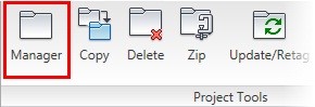
1: If the Project Manager is not displayed, on the Project tab, Project Tools panel, click Manager.
|
| |
2: If Panel_Layouts_NFPA is the active project, skip to step 6. If it is open but not active in the Project Manager, do the following:
■ Right-click Panel_Layouts_NFPA.
■ Click Activate.
■ Skip to step 6.
|
| |
3: In the Project Manager, click Open Project.
|
| |
4: Browse to where you installed the exercise files and select Panel_Layouts_NFPA.wdp. Click Open.
|
| |
5: From the Projects list, click the expansion node next to Panel_Layouts_NFPA to expand the drawing list.
|
| |
6: Right-click Panel_Layouts_NFPA_09.dwg. Click Open.
|
| |
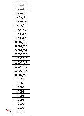
7: Zoom in to the right side of the panel layout drawing, just below terminal strip TS-B.
|
| |
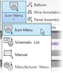
8: On the Panel tab, Insert Component Footprints panel, Icon Menu flyout, click Icon menu.
|
| |
9: In the Insert Footprint dialog box, under the Panel Layout Symbols preview window, click DIN Rail.

|
| |
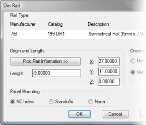
10: In the DIN Rail dialog box, do the following:
■ For Rail Type, select AB 199-DR1 from the list.
■ Under Origin and Length, for Length, click Pick Rail Information.
|
| |
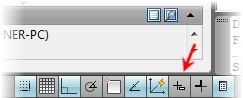
11: If necessary, on the status bar, toggle Dynamic Input to Off.
|
| |
12: In the drawing, do the following:
■ For the insertion point of rail, type "27.0,11.0"then press ENTER.
■ For the end point of rail, type "27.0,2.0"then press ENTER.
|
| |
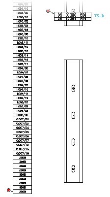
13: In the DIN Rail dialog box, do the following:
■ Under Orientation, click Vertical.
■ For Scale, type "1.0"
■ Under Panel Mounting, click NC Holes.
■ Click OK.
|
| |
14: In the Panel Layout - Component Insert/Edit dialog box, click OK.
The DIN rail is inserted.
|
| |
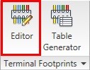
15: Edit the Terminal List:
On the Panel tab, Terminal Footprints panel, click Editor.
|
| |
16: If requested, in the Qsave dialog box, click OK.
|
| |
17: In the Terminal Strip Selection dialog box, select MCAB5 TS-D. Click Edit.
|
| |
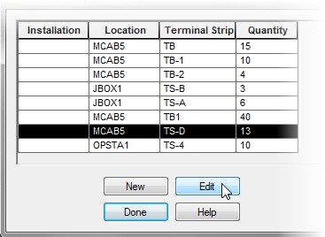
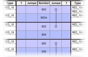
18: In the Terminal Strip Editor: MCAB5 TS-D dialog box, Terminal Strip tab, click the Number heading. This sorts the list by wire number.
|
| |
19: Under Destination, click Toggle Location.
|
| |
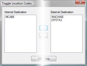
20: In the Toggle Location Codes dialog box, do the following:
■ From the Internal Destination list, select OPSTA3.
■ Click Toggle Internal to External >.
■ From the External Destination list, select MCAB5.
■ Click < Toggle External to Internal.
■ Click OK.
|
| |
21: Add Spares and Accessories:
On the Terminal Strip tab, from the terminal list, select the last row.
|
| |
22: Under Spare, click Insert Spare Terminal.
|
| |
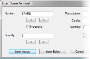
23: In the Insert Spare Terminal dialog box, do the following:
■ For Quantity, type "2"
■ Click Insert Below.
|
| |
24: On the Catalog Code Assignment tab, from the terminal list, select the two spare terminals.
|
| |
25: Under Catalog Codes, click Assign Catalog Number.
|
| |
26: In the Catalog browser (Table: TRMS) dialog box, do the following:
■ In the Search field, type 0115*
■ Select 0115 126.01 from the Catalog list.
■ Click OK.
|
| |
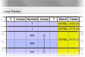
27: Select the top terminal in the grid.
|
| |
28: Under Spare, click Insert Accessory.
|
| |
29: In the Insert Accessory dialog box, for Number, enter 1
|
| |
30: Click Catalog Lookup.
|
| |
31: In the Catalog Browser dialog box, do the following:
■ In the Search field, type 0118*
■ Select 0118 499.23.
■ Click OK.
|
| |
32: In the Insert Accessory dialog box, click Insert Above.
|
| |
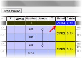
33: In the Catalog Code Assignment, select the new top terminal just inserted at the top of the grid.
|
| |
34: Under Spare, click Insert Accessory.
|
| |
35: In the Insert Accessory dialog box, do the following:
■ For Number, enter "1"
■ Click Catalog Lookup.
|
| |
36: In the Catalog Browser dialog box, do the following:
■ In the Search field, type 0103*
■ Select 0103 002.26.
■ Click OK.
|
| |
37: In the Insert Accessory dialog box, click Insert Above.
|
| |
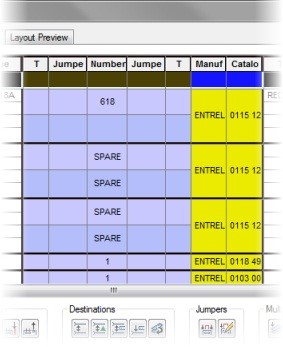
38: Repeat steps 28 through 37, selecting the bottom (Spare) terminal and inserting accessories below the existing components.
|
| |
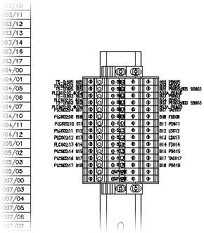
39: Insert a Graphical Terminal Strip:
In the Terminal Strip Editor dialog box, on the Layout Preview tab, click Graphical Terminal Strip.
|
| |
40: From the Graphical Layout list, select Wire Number Tag: Terminal.
|
| |
41: For Scale on Insert, enter "1.0"
|
| |
44: In the drawing, for the insertion point, enter "27.0, 10.5"then press ENTER.
|
| |
45: In the Terminal Strip Editor, click OK.
|
| |
46: In the Terminal Strip Selection dialog box, click Done.
|
| |
47: If requested, in the Qsave dialog box, click OK.
The terminals in the schematic are updated with the new catalog information.
|
| |
48: Insert a Tabular Terminal Strip (Table Object):
On the Panel tab, Terminal Footprints panel, click Editor.
|
| |
49: If requested, in the Qsave dialog box, click OK.
|
| |
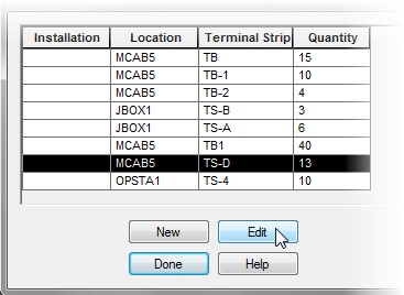
50: In the Terminal Strip Selection dialog box, select MCAB5 TS-D. Click Edit.
|
| |
51: In the Terminal Strip Editor dialog box, on the Layout Preview tab, click Tabular Terminal Strip (Table Object).
|
| |
52: Under Table Settings, do the following:
■ Click Layer.
■ In the Select Table Layer dialog box, select Terminal Tables from the list. Click OK.
■ For Table Title, select Terminal Strip ID (%T) from the list.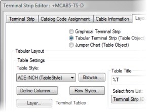
|
| |
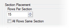
54: In the Terminal Strip Table Settings dialog box, under Section Placement, do the following:
■ Clear the All Rows Same Section check box.
■ For Rows per Section, enter "15"
|
| |
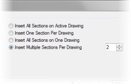
55: Click Insert Multiple Sections per Drawing.
|
| |
56: For Insert Multiple Sections per Drawing, enter "2"
|
| |
57: For Section Placement, do the following:
■ For X, enter "2.00"
■ For Y, enter "21.0"
|
| |
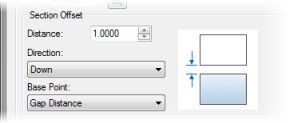
58: Under Section Offset, do the following:
■ For Distance, enter "1.0"
■ For Direction, select Down.
■ For Base Point, select Gap Distance.
|
| |
59: Under Drawing Information for Table Output:
■ For First Drawing Name, type "Panel_Layouts_NFPA_11"
■ For Template, click Browse and select ACAD_ELECTRICAL.dwt.
■ Click Open.
|
| |
60: Click Preview.
Notice that three new drawings will be created using these settings.
|
| |
61: In the Preview dialog box, click Done.
|
| |
62: In the Terminal Strip Table Settings dialog box, click OK.
|
| |
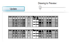
63: In the Terminal Strip Editor dialog box, click Update.
|
| |
64: Drag the Drawing to Preview slider and preview each of the drawings that will be created.
|
| |
66: In the Table(s) Inserted Task dialog box, click OK.
|
| |
67: In the Terminal Strip Editor dialog box, click OK.
|
| |
68: In the Terminal Strip Selection dialog box, click Done.
|
| |
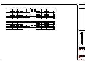
69: In the Project Manager, right-click Panel_Layouts_NFPA_11.dwg. Click Open.
|
| |
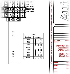
70: Insert a Jumper Chart (Table Object):
In the Project Manager, right-click Panel_Layouts_NFPA_09.dwg. Click Open.
|
| |
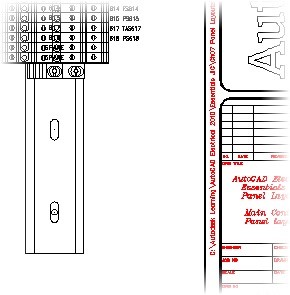
71: Zoom in to the lower-right corner of the drawing, just below the terminal strip you previously inserted.
|
| |
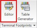
72: On the Panel tab, Terminal Footprints panel, click Editor.
|
| |
73: If requested, in the Qsave dialog box, click OK.
|
| |
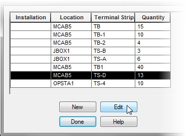
74: In the Terminal Strip Selection dialog box, select MCAB5 TS-D. Click Edit.
|
| |
75: In the Terminal Strip Editor dialog box, on the Layout Preview tab, click Jumper Chart (Table Object).
|
| |
76: Under Table Settings, Table Title, select Terminal Strip ID (%T) from the list.
|
| |
77: For Scale on Insert, enter "1.0"
|
| |
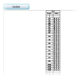
78: Click Update.
|
| |
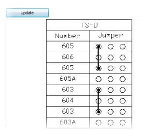
79: Select Display Only Jumpered Terminals.
|
| |
80: Click Update.
|
| |
82: In the drawing, enter an insertion point at approximately "28.0,5.0"
|
| |
83: In the Terminal Strip Editor dialog box, click OK.
|
| |
84: In the Terminal Strip Selection dialog box, click Done.
|
|


