| |
Wire Numbers and Leaders
| |
Objective: This exercise takes you through the process of inserting wire numbers automatically:
First, you add wire numbers throughout the drawing.
Then, as you enter a relay contact symbol, you see how wire numbers are updated automatically when components change the wire networks. You also add wire number copies.
Finally, you add wire numbers project-wide, sequencing through the entire project drawing list.
|
| |
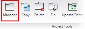
1: If the Project Manager is not displayed, on the Project tab, Project Tools panel, click Manager.
|
| |
2: If Schematic_Wiring_NFPA is the active project, skip to step 5. If it is open but not active, in the Project Manager, do the following:
> Right-click Schematic_Wiring_NFPA.
> Click Activate.
> Skip to step 5.
|
| |
3: In the Project Manager, click Open Project.
|
| |
4: Browse to where you installed the exercise files. Select Schematic_Wiring_NFPA.wdp. Click Open.
|
| |
5: Click the expansion node next to Schematic_Wiring_NFPA to expand the drawing list in the manager.
|
| |
6: Right-click Schematic_Wiring_NFPA_04.dwg then click Open.
|
| |
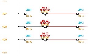
7: Zoom in to rungs 407-409.
|
| |
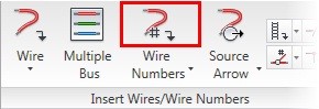
8: On the Schematic tab, Insert Wires/Wire Numbers panel, click Wire Numbers.
|
| |
9: You use all of the default settings. Click Drawing-Wide.
|
| |
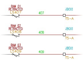
10: Notice that a single wire number is added to each of the wire networks in the drawing.
|
| |
11: Update Wire Numbers and Add Copies:
On the Schematic tab, Insert Components panel, click Icon Menu.
|
| |
12: In the Insert Component dialog box, select Relays/Contacts.

|
| |
13: Select Relay NO Contact.

|
| |
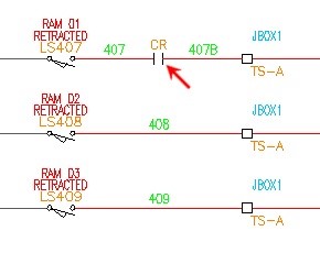
14: Select an insertion point on rung 407 between the LS407 limit switch and the TS-A terminal.
|
| |
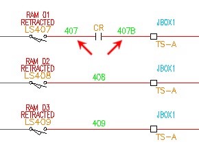
15: In the Insert/Edit Child Component dialog box, click OK to complete the insertion of the child contact.
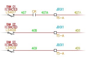
Notice that the new wire number is automatically added.
|
| |
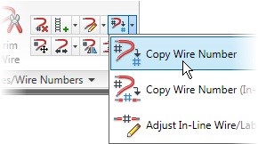
16: On the Schematic tab, Edit Wires/Wire Numbers panel, click Copy Wire Number.
|
| |
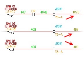
17: Select insertion points on rungs 407, 408, and 409 just to the right of the TS-A terminals.
Notice the different colors used for the extra wire numbers.
|
| |
18: Add Wire Numbers Projectwide:
On the Schematic tab, Insert Wires/Wire Numbers panel, click Wire Numbers.
|
| |
19: In the Wire Tagging dialog box, click Project-Wide.
|
| |
20: In the Wire Tagging (Project-wide) dialog box, click OK to accept all defaults.
|
| |
21: In the Select Drawings to Process dialog box, click Do All. Click OK.
|
| |
22: If requested, in the Qsave dialog box, click OK.
Notice that AutoCAD® Electrical processes each drawing that is selected and automatically adds wire numbers to all wire networks and cross-references.
|
| |
23: Save the drawing file. This completes the exercise.
|
|