Linking live data to a network
Any referenced datasets can be downloaded from "Module downloads" in the module overview.
Video quiz
Step-by-step Guide
Once the required information has been entered into the Live Data Configuration grid, it must be linked to the network. This shows the locations of live data points within the network.
- In the Model Group window, right-click Live Data Configuration and commit any changes you have made to the database. In this example, the changes are validated with no errors.
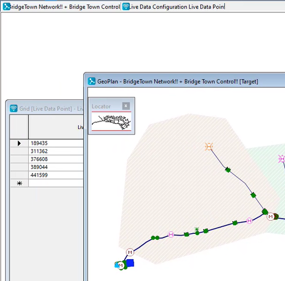
- Open the network and its associated control in the GeoPlan.
- To link the live data to your network, you MUST have the Live Data Configuration grid window open in the background of the workspace, with the network and control GeoPlan window in the foreground.
IMPORTANT: If the window positions are reversed, or if one is not open in the workspace, you will not be able to link the live data to the network.
To make sure the live data points match with the nodes in the GeoPlan:
- Select Network > Control > Link live data points to open the Link Live Data Points dialog box.
- Click both the Match with Asset ID and Match with Node/Link ID buttons.
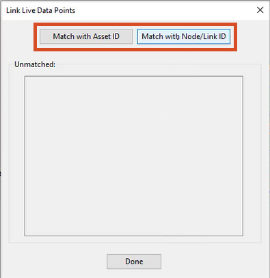
In this example, nothing is listed in the Unmatched: group box, meaning everything is correctly matched.
- Click Done.
- In the GeoPlan, notice that next to some objects, there are now icons that look like an orange square with a slightly tilted "Z" inside. This icon indicates that there is now a live data point attached to that object.
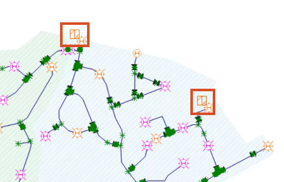
- Optional: Right-click the GeoPlan and click Selection > Select live data point objects from the submenu. This selects and highlights all objects with live data attached to them, so they are easier to see.
- In the toolbar, click the Clear selection button.
- Commit any outstanding changes to the network to the database.