Understanding flush sequences and the Flush Sequence Manager
Any referenced datasets can be downloaded from "Module downloads" in the module overview.
In InfoWater Pro UDF, a flush sequence is a series of operations that defines how a flush zone will be flushed. The goal is to start from a clean water source—such as a pump station or previously flushed sequence—and then select a hydrant to be flushed. Then, determine which valves need to be closed to increase the water velocity, so that it exceeds the minimum flushing (scouring) velocity in the pipes leading to the hydrant. The hydrant must remain open for at least the time needed to turn over the water in the pipes being flushed. This is referred to as minimum flushing time.
There are several important criteria for each flush sequence, including:
- Maintaining a minimum pressure inside the distribution system
- Minimizing the volume of water used
- Ensuring that water that has not yet been flushed does not get routed through a previously flushed area
Flush Sequence Manager:
InfoWater UDF issues detailed warnings when characteristics are not achieved by a flush sequence.
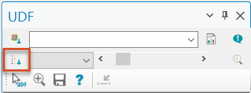
The Flush Sequence Manager is used to create and review flushing sequences, and can be opened from the UDF pane, by clicking Sequence Manager.
The Flush Sequence Manager is comprised of a few main areas:
- the toolbar
- a list of flush sequences
- a series of tabs for setting general options and specific operational criteria
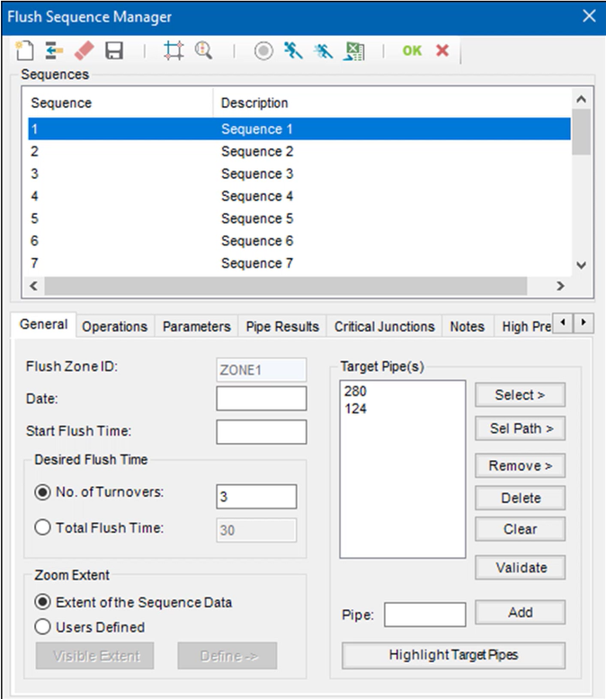
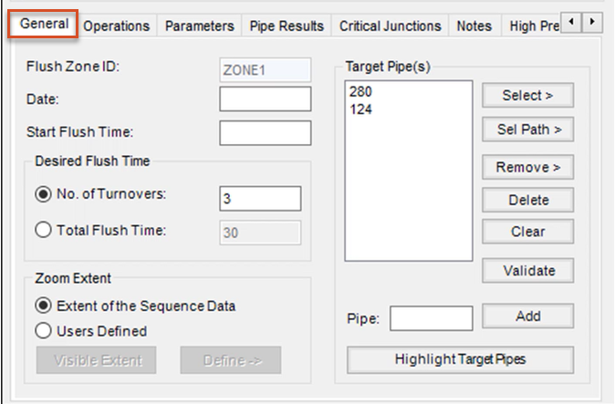
General Tab:
The Target Pipe(s) group box provides multiple selection methods for identifying the pipes to be flushed during that sequence.
Click Validate when finished adding IDs, to sort and validate the sequence.
Selecting an option under Desired Flush Time does not restrict the UDF simulation, but only generates a warning if the specified criteria are exceeded.
The Zoom Extent settings affect the zoom when printing a field journal and the display of sequences in the map.
Operations Tab:
Enter a primary hydrant to operate and, optionally, a secondary hydrant. Type these IDs directly into the fields, or click the corresponding arrow button to identify a hydrant graphically.
Once hydrants (and pipes) are identified, from the toolbar, click the Isolate Target Pipes tool to populate the Valves to Operate table automatically. A warning will be issued if any constraints are violated—for example, if all pipes in the sequence are not connected.
Valve IDs can also be entered manually, or click Close, Open, or Remove to select a valve graphically.

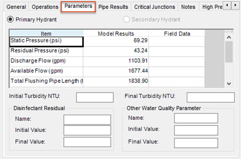
Parameters Tab:
Model results are populated for each sequence. Optionally, enter field data, which can be exported using the Export to Excel tool.
Initial and final values for turbidity, disinfectant residual, and one additional water quality parameter can also be entered.
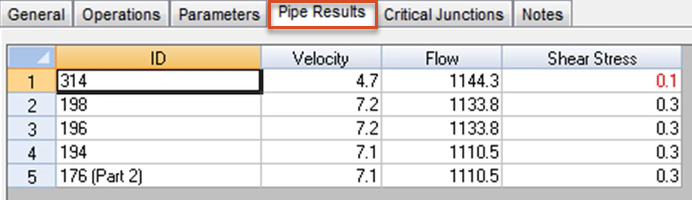
Pipe Results Tab:
This tab also populates model results for each sequence, including Velocity, Flow, and Shear Stress values for each pipe ID.
Violations of flush zone characteristics are highlighted in red.
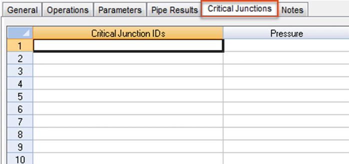
Critical Junctions Tab:
Junctions with pressure violations are displayed in this table.
The junctions must also be part of the flush zone under investigation.
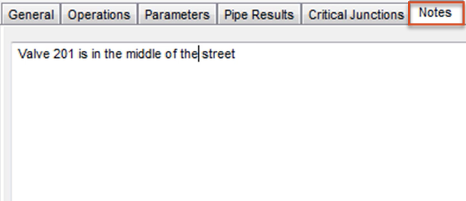
Notes Tab:
Flushing information entered here will appear in the UDF Flush Journal and will be saved with the UDF flush sequence data.
Run a UDF Simulation:
From the toolbar, click Run to run a UDF simulation of a single sequence, or click Batch Runs to run multiple sequences.
The Status tool displays the simulation status:
- Green indicates a successful simulation with no warning or errors.
- Yellow indicates that at least one warning message was generated.
- Gray indicates that the simulation was unsuccessful or has not been run.