Create transients from junction demand changes
Any referenced datasets can be downloaded from "Module downloads" in the module overview.
Step-by-step guide
InfoSurge Pro allows hydraulic transients to be created by providing a curve to alter pump and valve operations, as well as junction demand changes. Then, the simulation results from different operational conditions can be compared. In this example, transients are created from junction demand changes.
- Double-click the desired project .aprx file to open ArcGIS Pro.
- Click the InfoWater Pro tab to open the InfoWater Pro ribbon.
- In the Project panel, click Initialize.
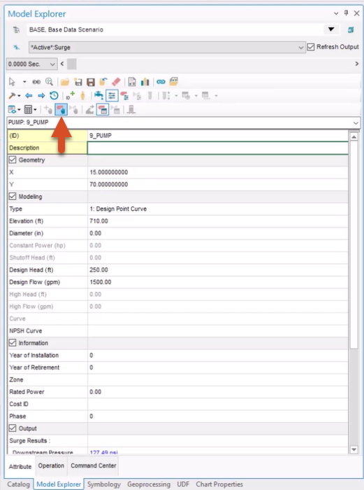
- From the Model Explorer, select Pump Operation Change.
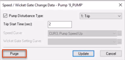
- In the Speed/Wicket Gate Change Data dialog box, click Purge to remove all previously entered settings.
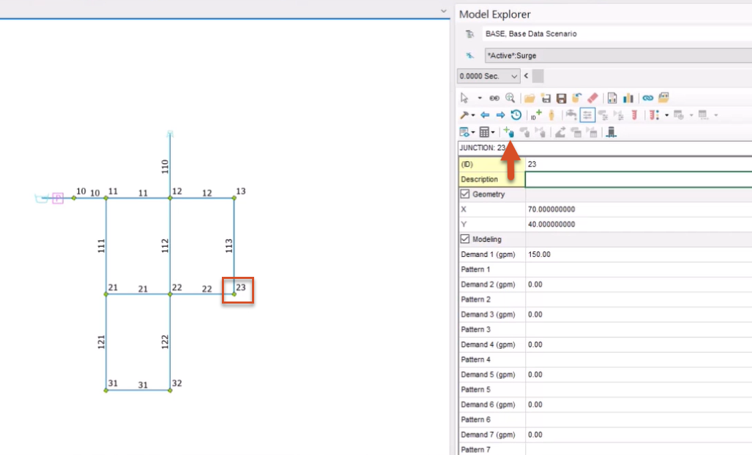
Next, create a curve to describe the junction demand over time. For this example, use Junction 23.
- From the map, zoom to and select Junction 23.
- From the Model Explorer, click Demand Change.
- In the Junction Demand Change Data dialog box, next to the Demand Change Curve drop-down, click Browse (…) to open the Curve dialog box.
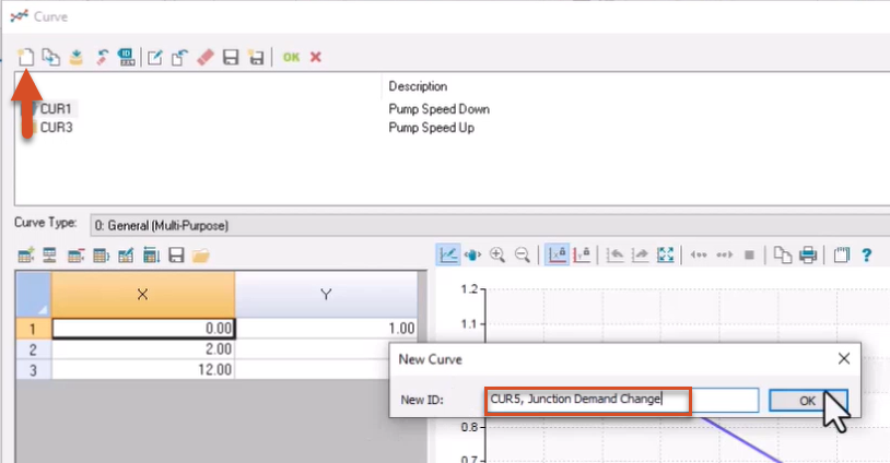
- Click New to create a new junction demand change curve.
- In the New ID field, enter “CUR5, Junction Demand Change”.
- Click OK.
- Click Set Rows.
- In the Curve popup, set the value to 3.
- Click OK.

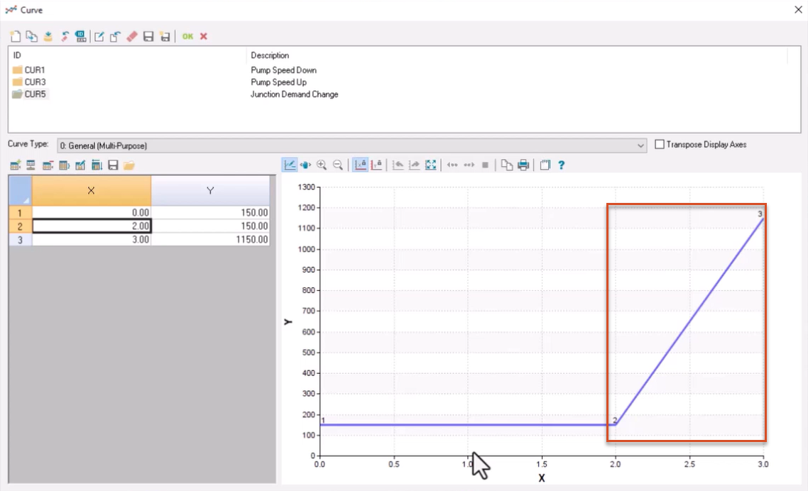
In the table, enter the following values in the X-axis column (time in seconds):
- In row 1, enter 0.00.
- In row 2, enter 2.00.
- In row 3, enter 3.00.
Enter the following values in the Y-axis column (demand in gallons per minute):
- In row 1, enter 150.00.
- In row 2, enter 150.00.
- In row 3, enter 1150.00.
Note that the updated graph indicates that after the first two seconds, the demand will increase from 150 to 1150 gallons per minute in one second. Such a demand increase may indicate fire flow.
- Click OK.
- In the remaining dialog box, select Create.
A surge analysis can now be performed.
- From the Model Explorer, click the Run Manager button.
- In the Run Manager dialog box, click the Run button to perform a surge analysis.
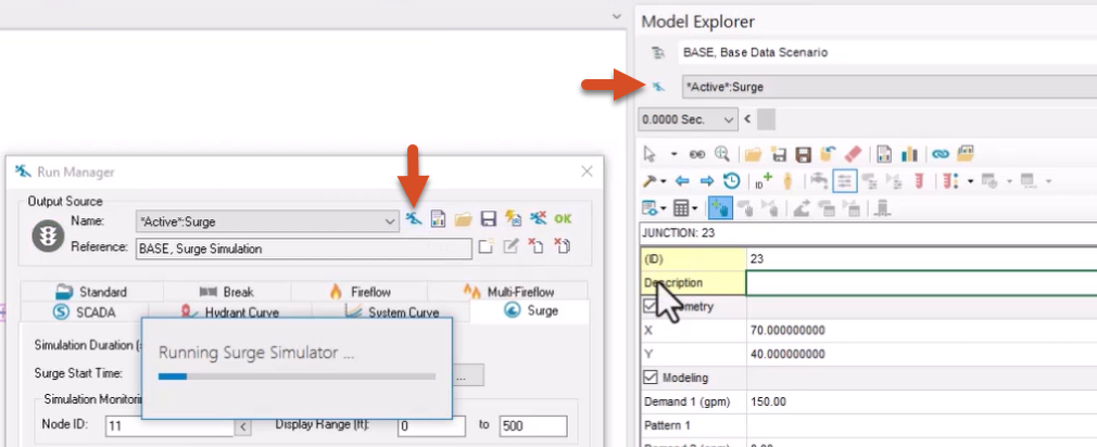
- Click OK to close the Run Manager.
- From the ribbon, View panel, click Report Manager.
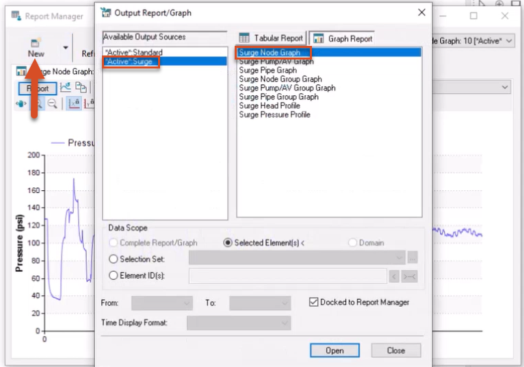
- In the Report Manager dialog box, click New.
- In the Output Report/Graph dialog box, under Available Output Sources, make sure *Active*.Surge is selected.
- From the Graph Report tab, pick Surge Node Graph.
- Click Open.
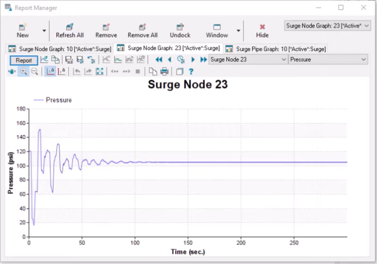
- From the map, select Junction 23 to view its pressure profile during the transient event.
- Close the Report Manager.
Next, run a surge analysis with a long junction demand change time.
- From the map, select Junction 23 again.
- From the Model Explorer, click Demand Change to open the Junction Demand Change Data dialog box.
- Next to the Demand Change Curve field, click Browse (…) to open the Curve dialog box.
- With the CUR5 curve ID selected, in the X-column, change the value in the third row to 12.00.
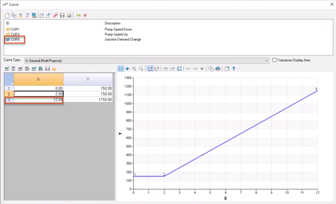
This increases the demand change time from 1 to 10 seconds.
- Click OK to close the dialog box.
- In the Junction Demand Change Data dialog box, click Update.
- From the Model Explorer, click the Run Manager button.
- In the Run Manager, click Run to perform a surge analysis.
- Click OK to close the Run Manager.
- From the ribbon, View panel, click Report Manager.
- From the Report Manager toolbar, click Refresh All.
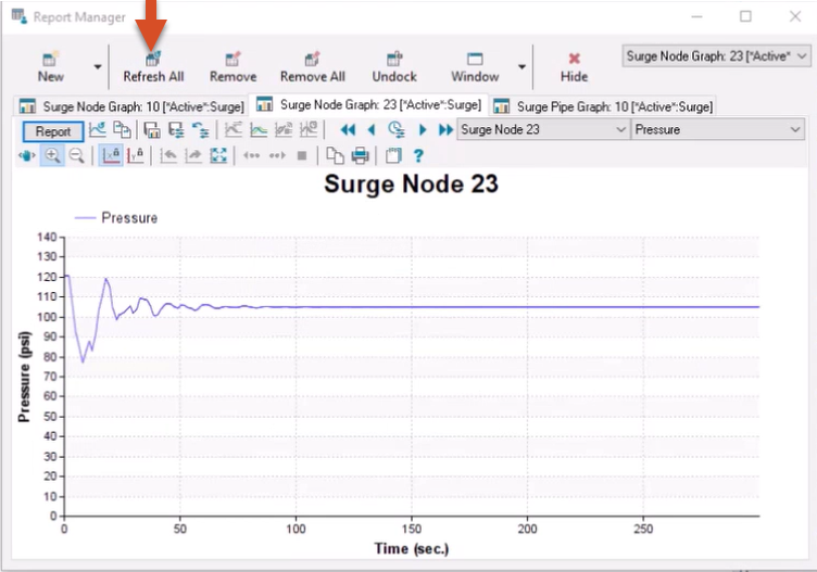
While there is still a transient event, allowing a slower rate of demand increase greatly reduce the pressure surge.
- Close the Report Manager.