Designing cellular storage
Any referenced datasets can be downloaded from "Module downloads" in the module overview.
Video quiz
Step-by-step Guide:
Cellular storage structures are a type of sustainable drainage solution (SuDS) that are typically crate-like structures with permeable walls that allow the storage and infiltration of water.
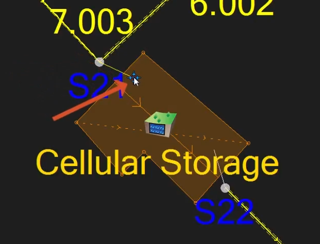
In this example, the outline for the cellular storage structure has already been imported. Pipe 6.003 will be replaced with the cellular storage structure.
- Open an InfoDrainage file that contains a drainage design in need of a cellular storage structure.
- In the Plan View, zoom in to the outline of the cellular storage structure, such as in the example file between manholes S21 and S22.
Delete the pipe inside the outline of the cellular storage structure:
- In the Toolbox, click the Select tool.
- Click pipe 6.003.
- Press DELETE.
To add the cellular storage structure:
- In the Toolbox, expand Stormwater Controls.
- Drag the Cellular Storage icon to the structure outline in the Plan View.
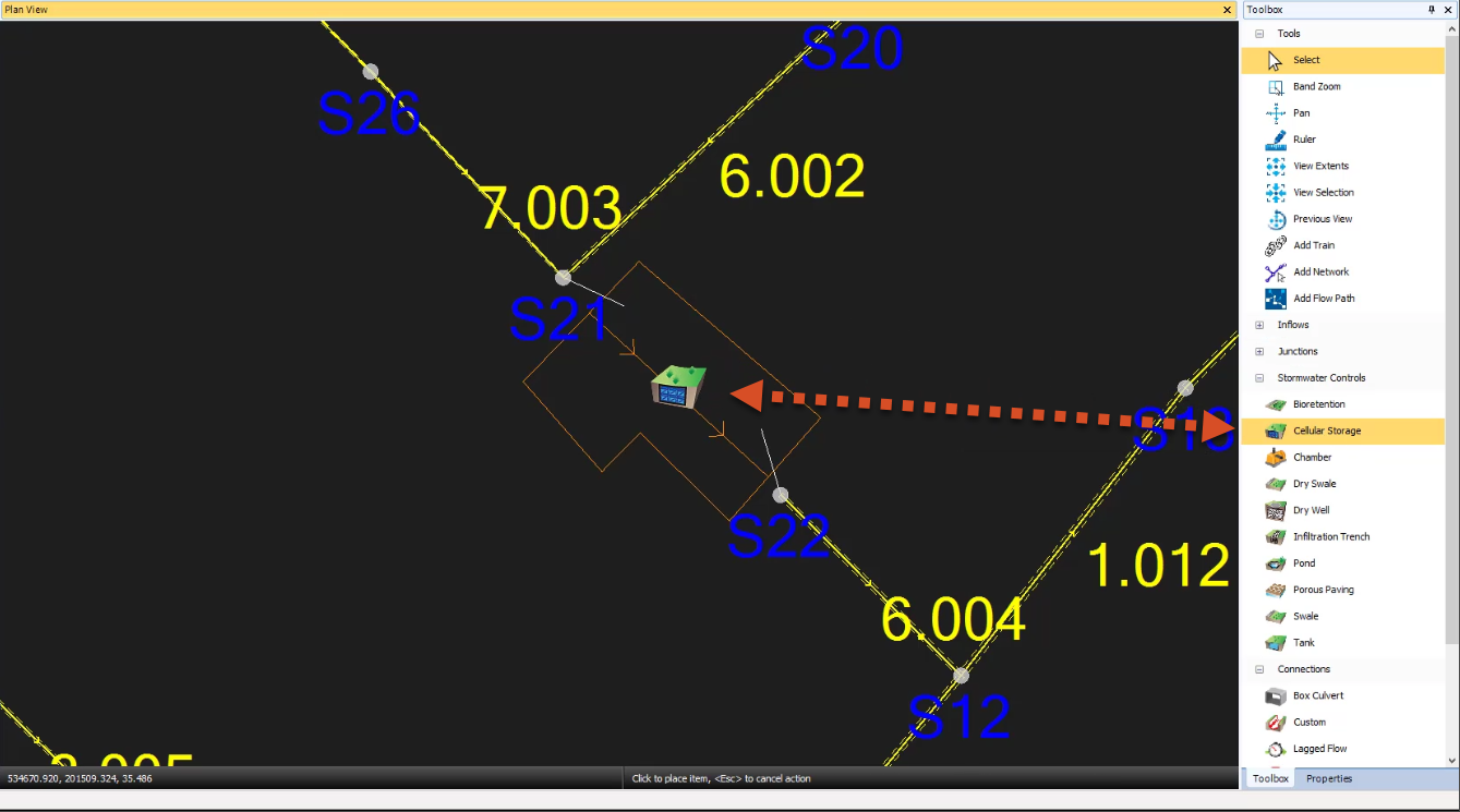
- Click two points inside the structure’s outline.
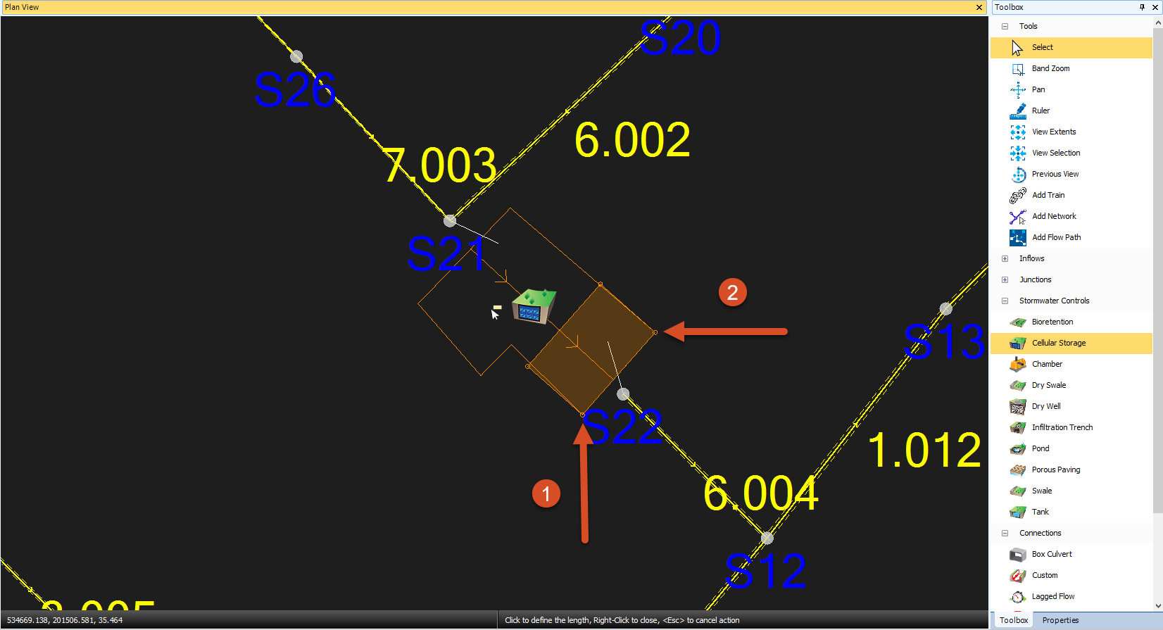
- Drag to create a rectangle that fills most of the outline.
- Click to finish the rectangle creation.
- From the Toolbox, click the Select tool again.
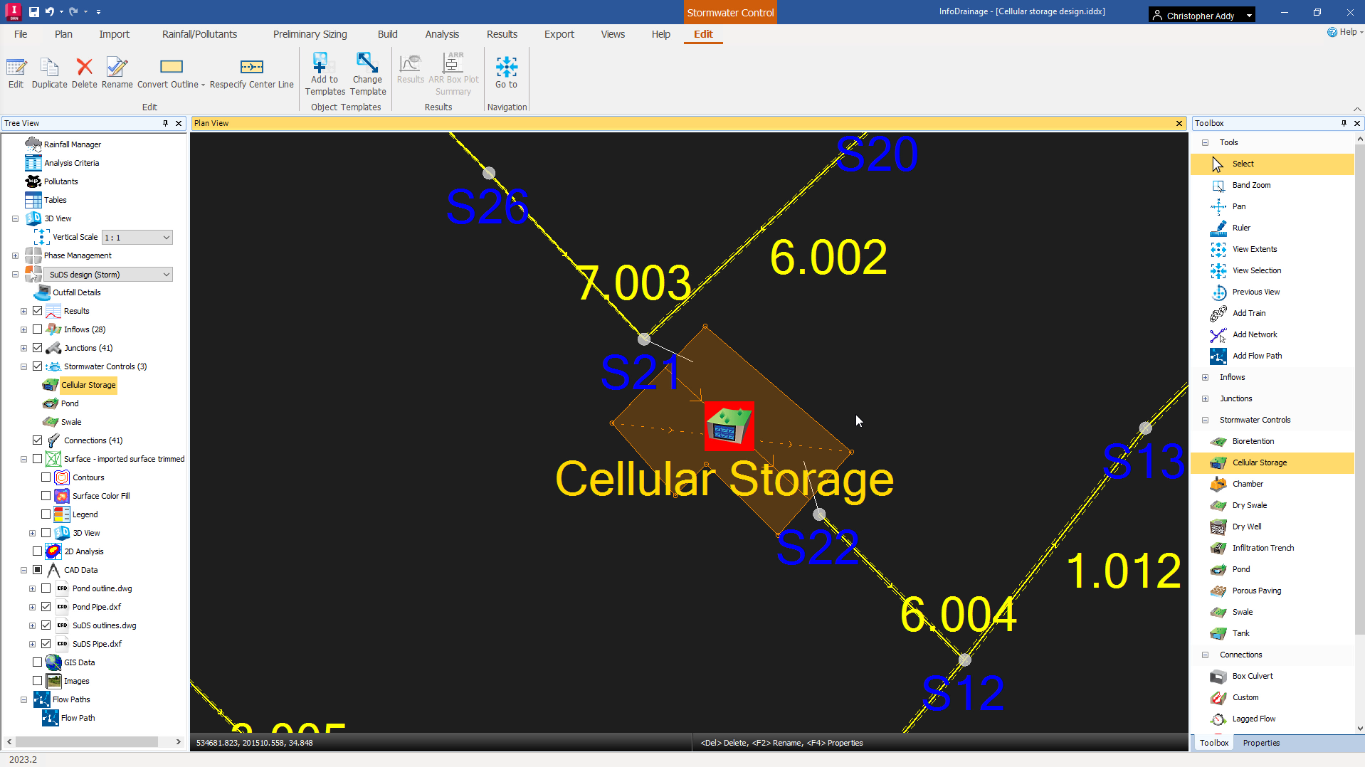
- Right-click the rectangle you just created and select Replace Outline > Free form.
- Click each vertex of the structure’s outline, in no specific order.
- Right-click anywhere to finish; the highlighted area fills the polygon.
IMPORTANT: Cellular storage structures are unusual, in that the parameters you enter do not necessarily correspond with the digitized area shown in the Plan View. Cellular storage structures are crates with predetermined sizes, so you must define the number of crates (unlike ponds and swales).
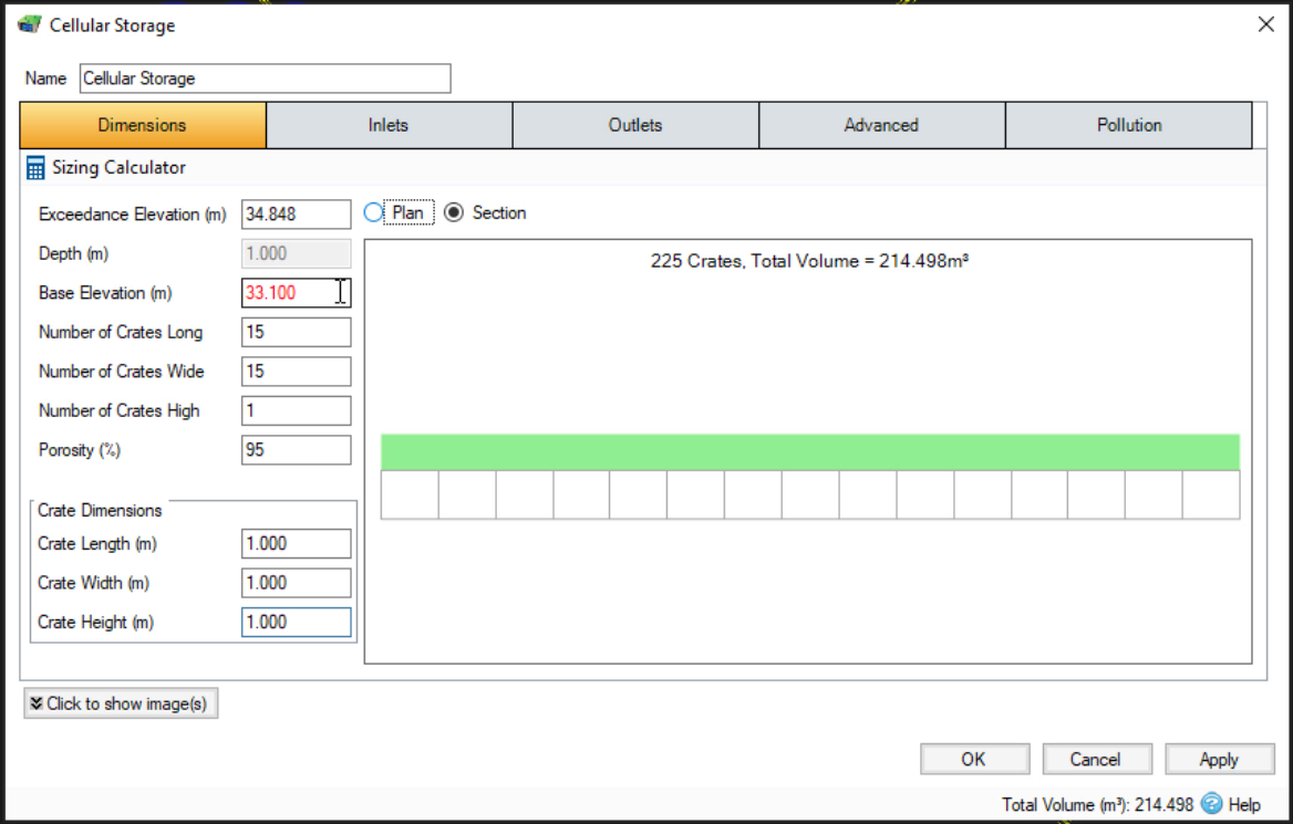
NOTE: In this example, the structure has an exceedance level of 34.848 meters, which is its lowest point. Also, all crates will have a length, width, and height of 1 meter.
- Double-click the Cellular Storage icon to open its properties.
- In the Cellular Storage dialog box, in the Base Elevation field, enter 33.10.
- Enter 15 for the Number of Crates Long.
- Enter 15 for the Number of Crates Wide.
- Enter 1 for the Number of Crates High.
- Type in a Porosity percentage of 95.
- Click OK.
To connect the drainage system pipes to the added cellular storage structure:
- For this example, ensure the file SuDS Pipe.dxf is loaded.
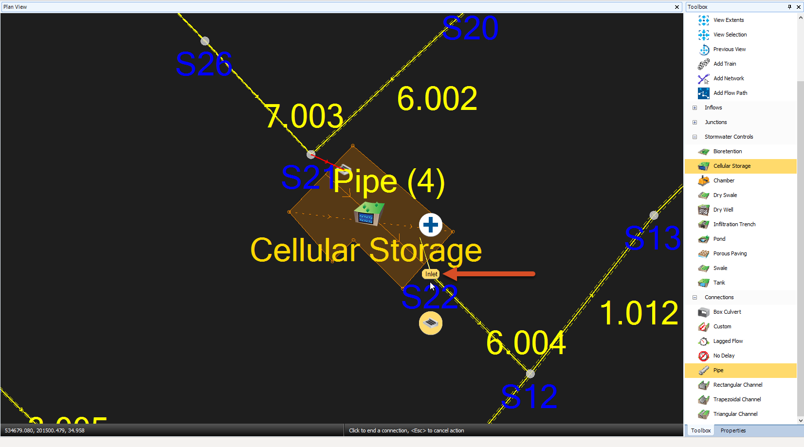
- From the Toolbox, click Pipe.
- Click manhole S21 and then click inside the cellular storage structure boundary at the other end of the line that indicates the planned pipe.
To connect another pipe at the downstream end:
- Click the line inside the boundary of the cellular storage structure.
- Make sure that “Inlet” is showing before you click to make the connection.
- Click manhole S22.
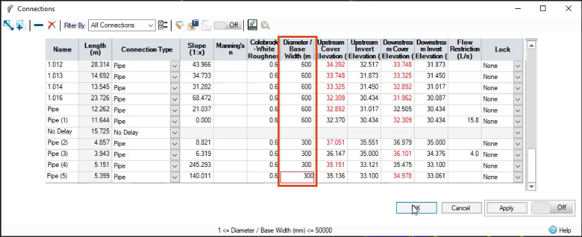
- Click either of the new pipes to open the Connections table.
- In the Diameter / Base Width column, enter a size of 300 mm for both these new pipes.
- In the Tree View, right-click Flow Paths and select Add.
- Create a flow path between manhole S23 and S22.
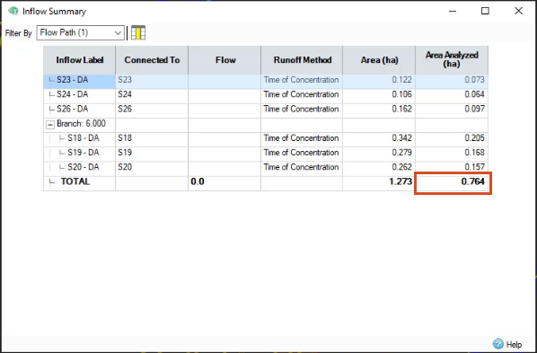
- With the new flow path highlighted, in the ribbon, Results tab, Reports panel, select Inflow Summary.
- Review the total area analyzed, 0.764 hectares.
- Close the dialog box.
- Click the Select tool again.
- Double-click the Cellular Storage icon to open its properties. It reports a total volume of 214.498 cubic meters.
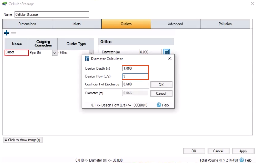
You now know the area and volume of the structure, but you still need to set a discharge limit to fully utilize its storage capacity. For this exercise, a Quick Storage Estimate has already determined a discharge limit of 9 liters per second, meaning you must size the outlet orifice to meet that limit.
- Click the Outlets tab.
- Change the Outlet Type to Orifice.
- Click Calculate Diameter.
- In the Diameter Calculator, enter a Design Depth of 1 meter.
- Enter a Design Flow of 9.
- Click OK to close the Diameter Calculator.
- Click OK to close the Cellular Storage Properties.
- In the ribbon, Analysis tab, Analysis panel, click Validate.
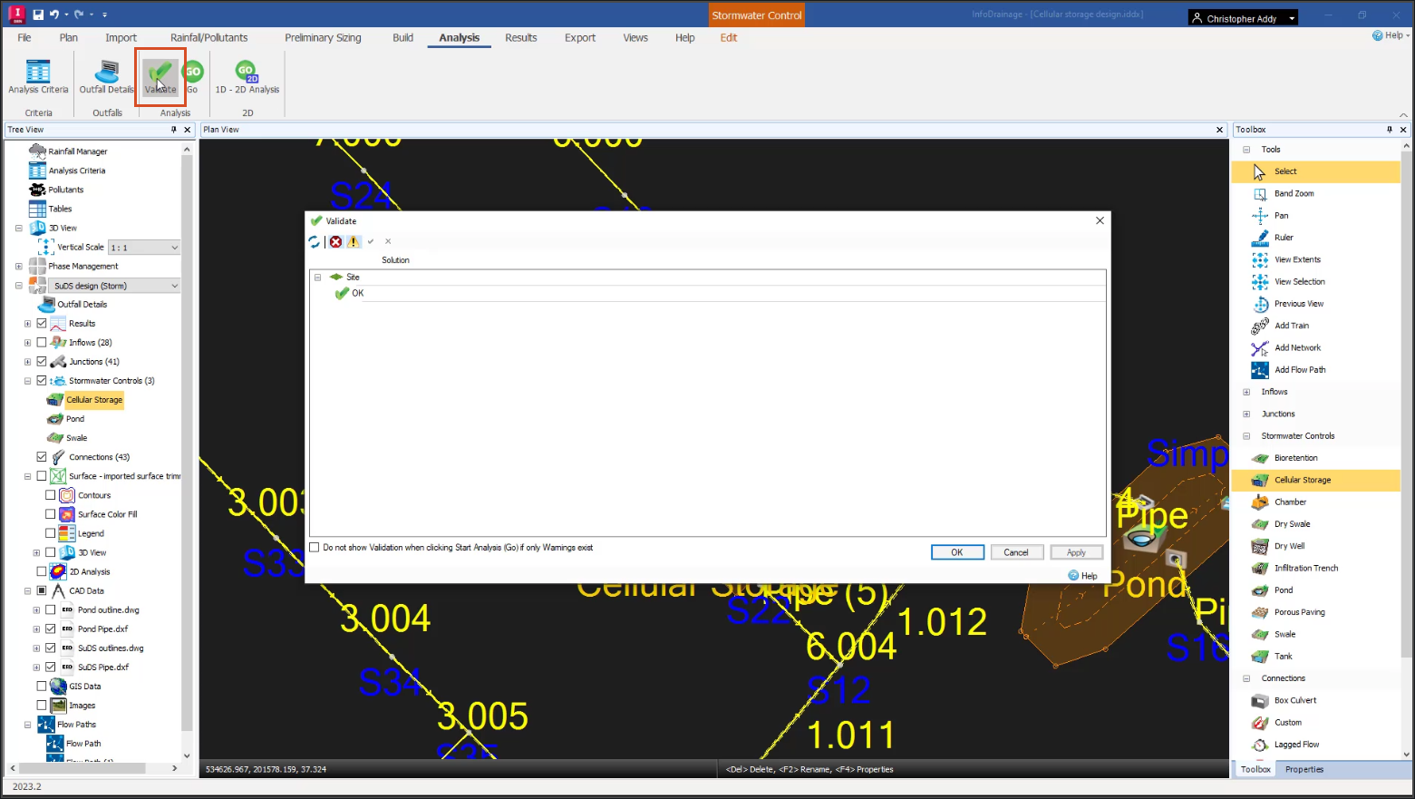
In this example, no errors are listed. The model now includes a cellular storage structure.
- Click OK.
- Save the file.