XREFS in Civil 3D
Any referenced datasets can be downloaded from "Module downloads" in the module overview.
XREFs - Exercise
- Open the drawing C:\Autodesk Learning\Setup C3D Projects\Course 1 - Data Management\Try-it- 1A.dwg. This is a blank drawing, but it has already been set up to the UTM-WGS 1984 datum, Zone 19 North, Meter; Cent. Meridian 69d W (UTM84-19N) coordinate system.
- Note that the current layer is ZZ-Xref.
- In the command line, type XR to start the XREF command.
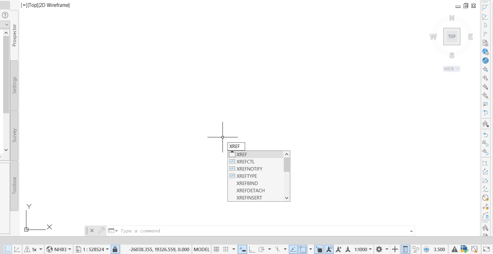
- In the top-left corner of the External References palette, click
 (Attach DWG).
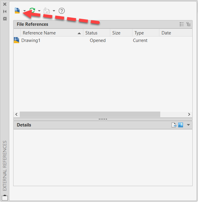
- In the Select Reference File dialog box, browse to the C:\Autodesk Learning\Setup C3D Projects\References\Drawings folder and select Existing Basemap.dwg.
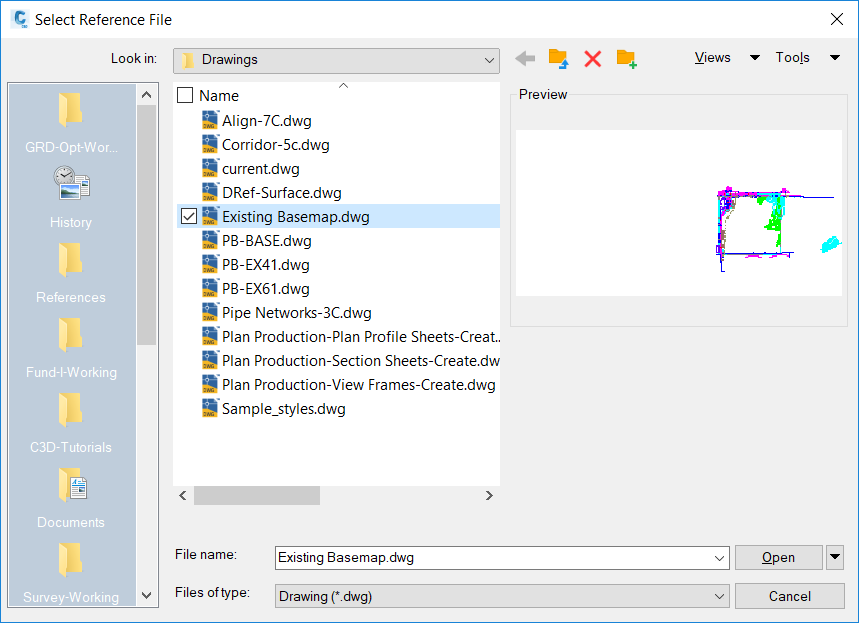
- Click Open.
- In the Attach External Reference dialog box, set the Reference Type to Overlay. Ensure that the Scale, Insertion point, and Rotation toggles are unchecked and that the Path type is set to Relative path.
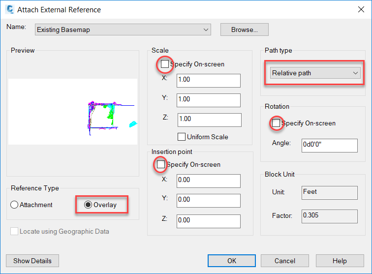
- Click OK.
- The referenced drawing is inserted at the 0,0,0 origin at full scale and no rotation. You will need to zoom to the extents of the drawing to see it. At the command line, type ZE.
- Note that the XREF is added to ZZ-Xref layer, which is the current layer.
- Repeat the procedure outlined above to attach the DRef-Surface.dwg drawing, which is located in the C:\Autodesk Learning\Setup C3D Projects\References\Drawings folder.
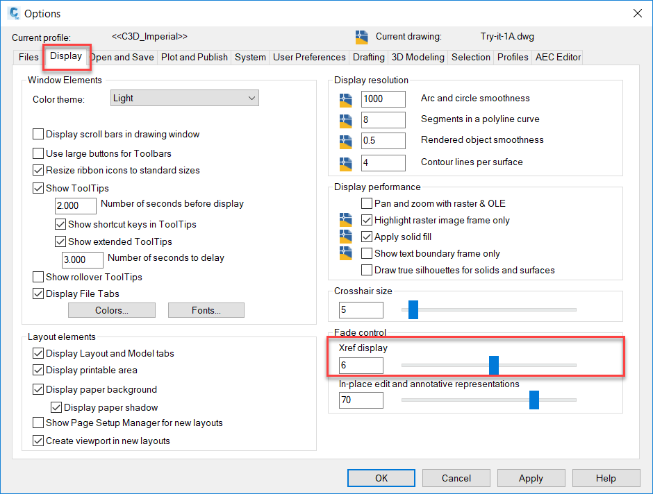
- XREFs will not fade like other objects when the layer’s transparency is lowered. Instead, both AutoCAD and Civil 3D can be configured to fade (or brighten) all XREFs in the drawing. In Civil 3D, type Options at the command line to open the Options dialog box.
- In the Options dialog box, go to the Display tab. In the lower-right corner, slide the Fade control lever for Xref display up to about 6 and click the Apply button. Note that the XREFs are now brightened. Continue to slide the lever and note the difference in the XREFs. Set the lever back to a value of 6 and click OK.
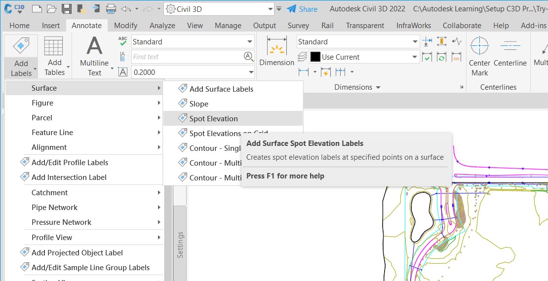
- In the Annotate tab>Labels & Tables panel, expand the Add Labels drop-down list and select Surface>Spot Elevation. You are prompted to select a surface. In the drawing area, click on a contour. Even though the surface resides in the Dref-Surface XREF and there are no DREFs for the surface, Civil 3D still can read the surface information.
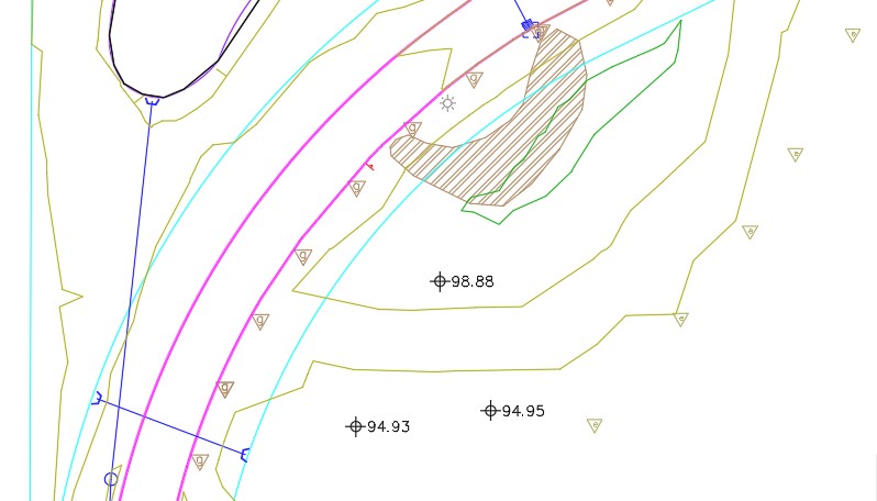
- Click somewhere within the surface area to add a spot elevation label. Click a few more places to add more labels, then press the <Esc> key to terminate the command.
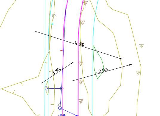
- Expand the Add Labels drop-down list and select Surface>Slope.
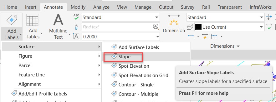
- Select a contour to designate the surface to be labelled. Select the Two-point label option at the command line, then define two points somewhere within the contours of the drawing to add the two-point slope label. Click a few more places to add more labels, then press the <Esc> key to terminate the command.

- Save the drawing.