| |
Completion of the Icon Menu System Lesson.
| |
Objective: In this exercise, you add an icon function to the Insert Component icon menu. Adding an icon function inserts a custom symbol. Then you add a submenu, and copy the icon function from the main page of the Insert Component icon menu and paste it onto the submenu.
|
| |
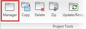
1: If the Project Manager is not displayed, on the Project tab, Project Tools panel, click Manager.
|
| |
2: If Custom_Components_NFPA is the active project, skip to step 6. If it is open but not active, in the Project Manager, do the following:
■ Right-click Custom_Components_NFPA.
■ Click Activate.
■ Skip to step 6.
|
| |
3: In the Project Manager, click Open Project.
|
| |
4: Browse to where you installed the exercise files and select Custom_Components_NFPA.wdp. Click Open.
|
| |
5: From the Projects list, click the expansion node next to Custom_Components_NFPA to expand the drawing list.
|
| |
6: Right-click Custom_Components_NFPA_04.dwg. Click Open.
|
| |
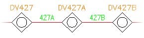
7: Zoom in to DV427 on rung 427.

|
| |
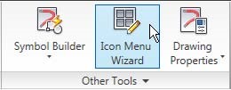
8: On the Schematic tab, Other Tools panel, click Icon Menu Wizard.

|
| |
9: In the Select Menu File dialog box, make sure ACE_NFPA_MENU.DAT is selected. Click OK.
|
| |
10: In the Icon Menu Wizard dialog box, in the NFPA: Schematic Symbols preview window, right-click in an empty area. Click Add Icon > Component.
|
| |
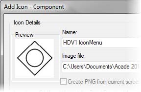
11: In the Add Icon - Component dialog box, do the following:
■ For Name, type HDV1 IconMenu
■ For Image File, click Browse.
■ Browse to the project directory. Select HDV1_IconMenu.png
■ Click Open.
|
| |
12: Under Block Name to Insert, do the following:
■ Click Browse.
■ Browse to the project directory. Select HDV1_IconMenu.dwg
■ Click Open.
|
| |
13: Click OK. The new icon is created in the preview window.
|
| |
14: In the Icon Menu wizard, click OK to close the dialog box.
|
| |
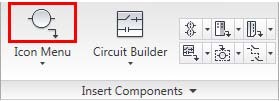
15: On the Schematic tab, Insert Components panel, click Icon Menu.
|
| |
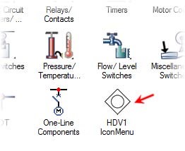
16: In the Insert Component dialog box, NFPA: Schematic Symbols preview window, click HDV1 IconMenu. Specify the insertion point on rung 427, just to the right of the original.
|
| |
17: In the Insert/Edit Component dialog box, click OK to end the insertion.

|
| |
18: On the Schematic tab, Other Tools panel, click Icon Menu Wizard.
|
| |
19: In the Select Menu file dialog box, make sure ACE_NFPA_MENU.DAT is selected. Click OK.
|
| |
20: In the Icon Menu Wizard, right-click in the NFPA: Schematic Symbols preview window. Click New Submenu.
|
| |
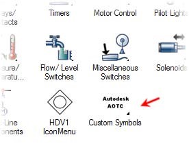
21: In the Create New Sub-Menu dialog box, do the following:
■ For Name, type Custom Symbols
■ For Image File, click Browse.
■ Browse to the project directory. Select Custom_Symbols.png
■ Click Open.
■ For Menu Title, type Custom Symbols
■ Click OK.
|
| |
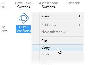
22: In the NFPA: Schematic Symbols preview window, right-click HDV1 IconMenu. Click Copy.
|
| |
23: In the Menu list, select Custom Symbols.
|
| |
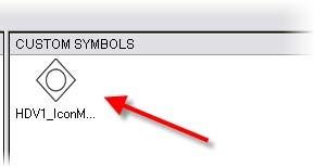
24: Right-click in the Custom Symbols preview window. Click Paste.
The HDV1 IconMenu icon is displayed.
|
| |
25: Click OK to exit the Icon Menu wizard.
|
| |
26: To test your new submenu, do the following:
■ On the Schematic tab, Insert Components panel, click Icon Menu.
■ In the Insert Component dialog box, click Custom Symbols.
■ In the Custom Symbols dialog box, click HDV1 IconMenu.
■ Specify an insertion point on rung 427, just to the right of DV427A.
■ In the Insert/Edit Component dialog box, click OK.
|
|


