00:08
Now let's dive in to point-to-point wiring.
00:11
Point-to-point wiring can mean a lot of different things
00:13
throughout your electrical package.
00:15
It could be that you're in a composite drawing like the one
00:19
This is a blend of ladder diagrams
00:22
along with components that are going
00:24
to be pointed to one another.
00:26
You'll see what I mean in just a second.
00:28
The other option is perhaps you don't use a ladder at all,
00:31
and you're just going directly from one component to another.
00:34
What you're going to learn in this lesson
00:36
will show you how to do that either way.
00:39
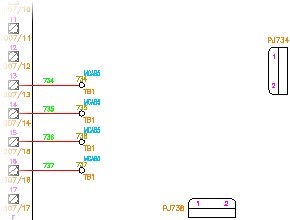
The most basic form of this is when
00:41
we zoom up on the terminals that you see here and the connectors
00:47
What I'm going to do is to start making connections to them.
00:49
And what I want you to focus in on
00:51
is the automatic wire routing that AutoCAD Electrical
00:55
So I'm going to start with a wire.
00:57
This time, I'm actually going to change the wire type.
00:60
So I want you to see how I do that.
01:01
I come down to the command prompt--
01:04
And I can click on this wire type button,
01:07
and I can switch to a different wire type.
01:09
So this time, I'm going to choose RED_18 gauge.
01:14
Now all of the wires that I use, unless I go in and switch that
01:17
again, is going to be under that RED_18 gauge layer.
01:21
Now wires are just AutoCAD line entities not PE lines
01:27
or any other kind of line entity but truly
01:29
the AutoCAD line utilizing layers
01:33
that have been predefined in our AutoCAD Electrical settings
01:37
to be electrical wires.
01:39
This is how it knows how to put wire numbers on them, how
01:42
to do wire from twos-- it's where all of the automation
01:45
then can happen when we want to run reports
01:47
on any of our projects set.
01:50
So now what I'm going to do is connect to this terminal.
01:54
And I'm just going to come straight down and connect
01:58
And I'm going to keep going across here.
01:60
And I want you to see how it automatically routes these.
02:02
Notice I didn't have to click where I wanted it to go.
02:06
It would just automatically choose that route for me.
02:09
Now you can choose along the way where you
02:11
want those routes to happen.
02:12
You're not forced to do it this way,
02:14
but this is the beauty that it does automatic collision
02:17
detection and then will auto route itself
02:19
around those collisions.
02:20
If you feel like the auto route was a little closer
02:23
than you wanted it to be-- for instance, this one.
02:25
There are great commands for editing our wires
02:28
like Scoot, where we can right click and just choose Scoot.
02:31
And it's a bit of a move mixed with a trim and an extend.
02:35
So if you think of all these little commands and electrical
02:37
as a combination of all of the commands we'd
02:40
have to do in Vanilla AutoCAD, you'll
02:42
see the power of such a simple command like Scoot.
02:46
So I can keep adjusting this.
02:48
And what you're seeing it do is extend one wire,
02:50
trim another wire, and then move itself across
02:53
to be able to give you that expansion.
02:56
And that's the beauty of using the electrical tools as
02:59
opposed to trying to go back to utilize our core AutoCAD
03:01
tools that we're all so used to doing--
03:04
not that they can't be done, just a lot more effort
03:07
OK, so that's the automatic wire routing.
03:09
Let's take a look at some of the other wiring tools
03:12
that we can have with point-to-point.
03:14
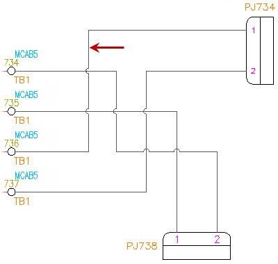
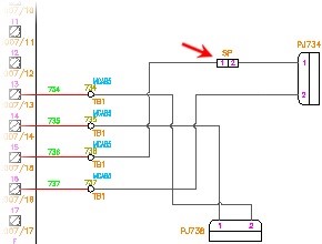
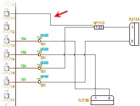
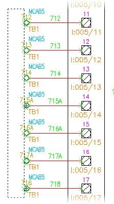
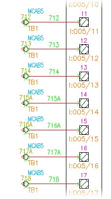
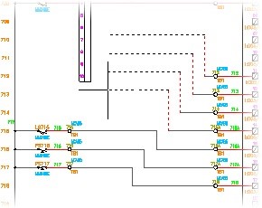
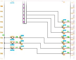
So if we look over here at all of the terminals
03:17
that are listed here, and you can
03:19
see the Connector and the additional terminals
03:21
that I have on the left hand side.
03:23
I want to connect all of those, but I
03:25
want to do it in one shot.
03:27
I don't want to have to go manually one by one
03:29
to connect each one of them.
03:30
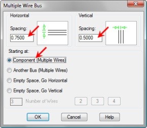
In this case, we have something called a Multiple Bus.
03:34
If I click on that, I can choose that I want
03:36
to go component-to-component.
03:39
Now I can also then say, OK on this.
03:43
and I am going to turn off, in this case, my snap settings
03:47
because I need to get pretty close to these components.
03:50
So I am going to grab the left-hand Connector
03:54
Be careful with terminals.
03:56
They have connection points in all four quadrants.
03:59
So if you noticed I had to be really careful about where
04:01
I grabbed that crossing window to ensure I only
04:04
made a wire connection on the left-hand terminal
04:08
point as opposed to going through the top and the bottom
04:11
So things to be aware of when you're dealing
04:13
with terminals themselves.
04:14
Most of our other components don't have that many connection
04:19
When I hit Enter, I automatically
04:20
get wiring across all of them.
04:23
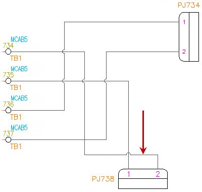
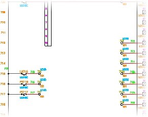
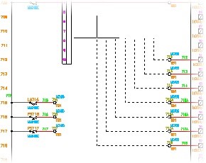
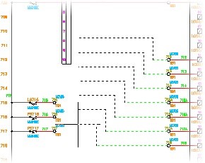
Now I can starter make turns for where
04:25
I want to take this wire path.
04:27
So in this case, I want to take it up slightly.
04:30
And I'm going to pull it out enough that it's not
04:33
If you noticed on line 712, I don't want it cutting back
04:38
I'm going to bring it up, and then I'm
04:39
going to turn it again.
04:41
So if you're reading the command prompt at the bottom,
04:43
you can see that there's an option to Continue or to Flip.
04:48
The Flip would be if I was getting
04:49
this view in the direction that I wanted to go
04:52
and I didn't want them to be overlapped like that.
04:54
So that's the reason to use Flip.
04:56
But up here, I'm going to then hit C and Enter for Continue.
05:00
And it's going to give me another set of arrows
05:03
so that I can keep building how I want this route to go.
05:08
And so I'm going to zoom up and just
05:09
start making connections one by one through these terminals,
05:14
and then ultimately into this Connector,
05:16
and the Connector auto routes to it.
05:18
So it gave me all four connection points
05:22
So those are some of the great point-to-point tools
05:24
that we have with an electrical.
05:26
Please take a moment to go do the exercise
05:29
on point-to-point wiring.