Control visibility of structural elements
Any referenced datasets can be downloaded from "Module downloads" in the module overview.
Control the visibility of the structural elements - Exercise
Task 1: Change the detail level
- Start Autodesk Revit 2021 and open the Medical-Center-Structure-Design-Visibility.rvt file. The connections imported from Advance Steel are displayed as green lines and circles.
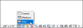
- From the View Control Bar below the graphics window, click Detail Level > Fine, as shown in the figure below. The display of the elements starts to change as they are displayed with the fine detail level.
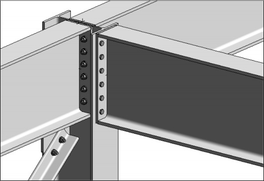
- Navigate closer to a connection and notice the plates and bolts of the connections displayed, as shown below.
- Interrogate the model and review the connections imported from Advance Steel.
- Click on an element of any connection.
- From the Properties palette > Detailed Parameters, click Edit. The dialog box of that connection is displayed.
- Review various categories and tabs of that connection and notice the similarities between the dialog box in Revit and that in Advance Steel.
Task 2: Add the bracing connection to the model
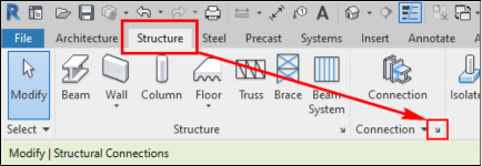
- From the Structure ribbon tab > Connection ribbon panel, click the Connection Settings button, which is the arrow on the lower right corner, as shown below. The Structural Connection Settings dialog box is displayed.
- From the Connection Group drop-down list labeled as 1 in the figure below, select General bracings.
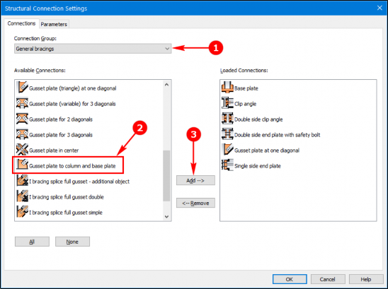
- From the Available Connections area, scroll down and select the Gusset plate to column and base plate connection labeled as 2 in the figure above and then click the Add button labeled as 3 in the figure above. The selected connection is added to the Loaded Connections area.
- Click OK in the dialog box to return to the Revit window.
- Navigate closer to the ground level column where the bracing needs to be connected.
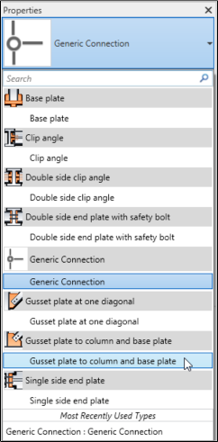
- From the Structure ribbon tab > Connection ribbon panel, click the Connection button. The Properties palette shows Generic Connection.
- In the Properties palette, click the Generic Connection drop-down list and select Gusset plate to column and base plate, as shown below.
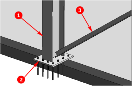
- Select the column labeled as 1 in the figure below as your first selection.
- Hold down the CTRL key and select the base plate labeled as 2 in the figure below as the second selection.
- With the CTRL key still held down, click the bracing section labeled as 3 in the figure below.
- Press ENTER. A connection is added and an error message is displayed.
The reason the error message is displayed is that the bracing section is selected as the second element of the joint and not third. - Drag the 3 tag and drop it on the bracing section. The connection selection is reordered and the preview of the connection is displayed, as shown below.

- In the Properties palette, select the Override by Instance check box. The Edit button on the right of the Detailed Parameters option is activated.
- Click the Edit button on the right of the Detailed Parameters option. The Gusset plate to column and base plate dialog box is displayed.
- From the General category > Gusset plate shape tab, select variable from the 2. Shape at beam/plate drop-down list labeled as 1 in the figure below.
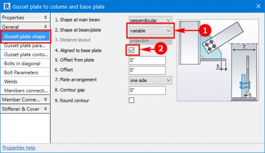
- Select the Aligned to base plate check box labeled as 2 in the figure above.
- Close the dialog box.
- Add this connection to the other column as well.
- Save the Revit project.
Task 3: Control the visibility of the connection elements
- Type VV to invoke the Visibility Graphics dialog box.
- In the Model Categories tab, scroll down and expand the Structural Connections category. The connection elements are displayed with the check mark on their left, as shown below.
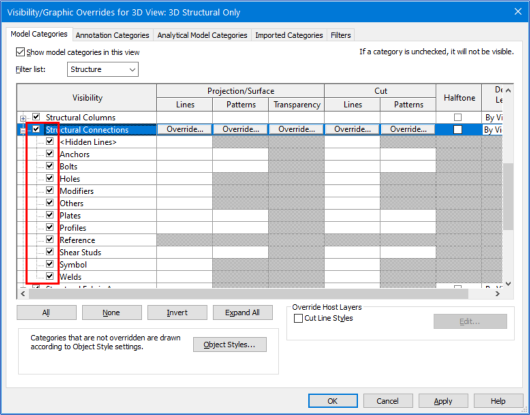
- Deselect the check box on the left of the Structural Connection category and then click Apply. The connection elements are no more displayed in the model.
- Select the check box again and click Apply. The connection elements are displayed.
- Close the dialog box.
- Save the file.