Creating perspective views for rendering purposes
Any referenced datasets can be downloaded from "Module downloads" in the module overview.
Create a perspective view - Exercise
A perspective view is basically a view of the room as if you were standing there looking at the room as a first person. Perspective views are the best way to get your design to an actual storyboard, or at least into a presentation. You can render any 3D view, but a perspective view is best suited to capture your design intent.
To create a perspective view, follow these steps:
- Open Revit.
- Open the Small Medical Center.rvt model from your project files.
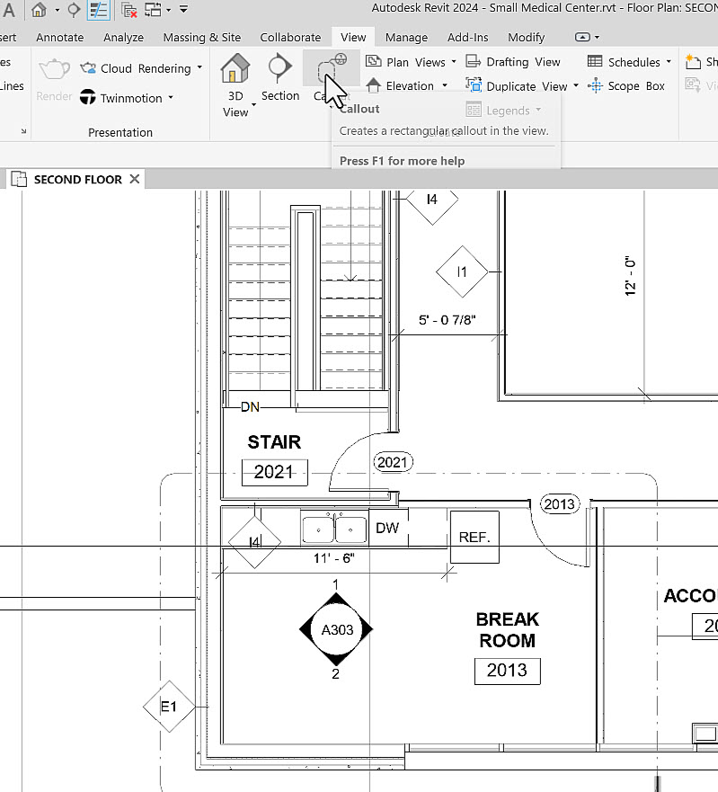
- In the Project Browser, open the SECOND FLOOR floor plan and zoom in to the break room in the lower-left corner of the view.
- In the View tab>Create panel, select Callout.
- Draw a rectangular callout as shown below.
- Double-click on the callout bubble to make the callout view active.
- In Properties, rename the view SECOND FLOOR BREAKROOM.
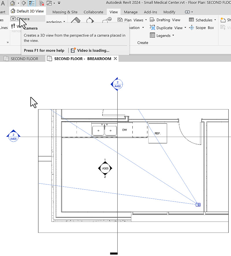
- In the View tab>Create panel, expand 3D View and select Camera. (You can also access this from the Quick Access toolbar, as shown below.)
- For the first point, click a point in the lower-right corner of the room.
- For the second point, click a point that is beyond the walls of your view (as shown below). This ensures the perspective will be as wide as possible to capture as much of the room within the view as it can.
- You now have a perspective view of your room. In Properties, rename the view SECOND FLOOR BREAKROOM. Note that it is available in the Project Browser under the 3D Views branch.
- Click on the crop region. Note how it surrounds the view and has four blue circular grips that appear, as shown below.
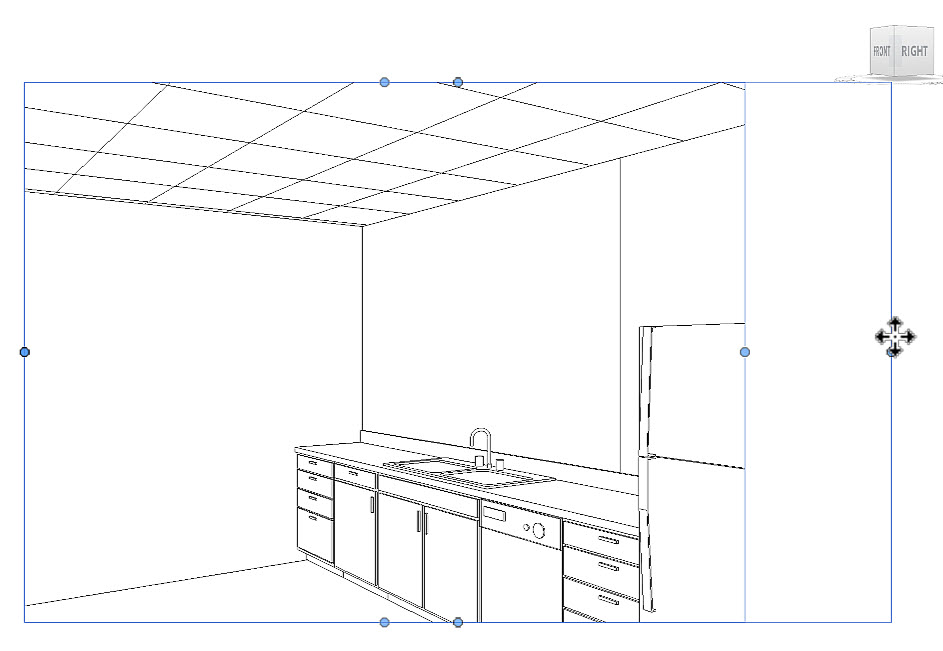
- Pick and hold the blue grips and drag the extents until you have the widest possible view that makes sense.
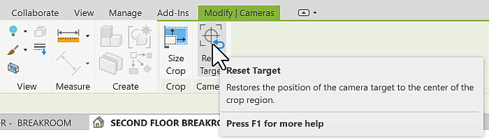
- As you resize the crop region, the display gets distorted. Once you have the proper size for the crop region, in the contextual tab>Camera panel, select Reset Target.
- In the Navigation Bar, select the Navigation Wheel.
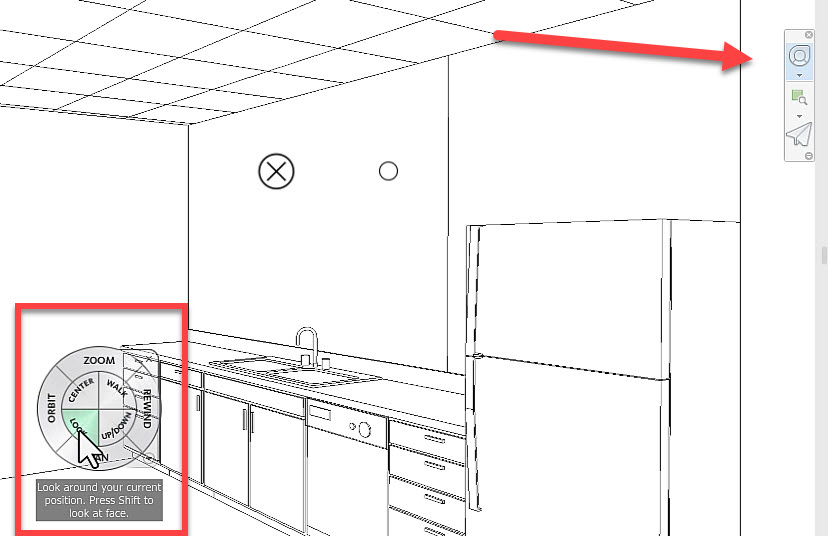
- In the Navigation Wheel, do the following:
- Click the Look section and drag your mouse around the screen to change your target. Release the mouse.
- Click the Walk section and drag your mouse around the screen to change your camera position. Release the mouse.
- Click the Up/Down section and drag your mouse up and down the screen to change the elevation (eye level) of the camera. Release the mouse.
- Click the Zoom section and drag your mouse around the screen to change the focal area of the camera. Release the mouse.
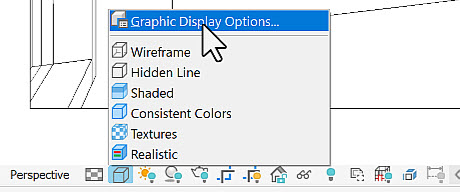
- In the View Control Toolbar, in the Visibility Graphics drop-down list, select Graphic Display Options…, as shown below.
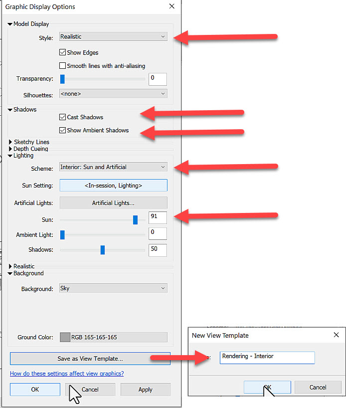
- In the Graphic Display Options dialog box, set the following (as shown below):
- Set the Style to Realistic.
- Select both Cast Shadows and Show Ambient Shadows.
- In the Lighting area, set the Scheme to Interior: Sun and Artificial.
- Set the Sun intensity to around 90.
- Click Save as View Template…. In the New View Template dialog box, enter Rendering - Interior for the name and click OK.
- Click OK to close the Graphic Display Options dialog box.
- The view is rendered with the settings you just set. Note that there are some materials already in the model – others will be added in the next exercise.
- Save the model.