Insert a standard belt drive
Any referenced datasets can be downloaded from "Module downloads" in the module overview.
Insert a belt drive - Exercise
- From the project files, open Belt Driven Gear Reducer 3.dwg.
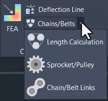
- In the Content tab>Calculation panel, click the drop-down arrow next to Chains/Belts and select Sprocket/Pulley.
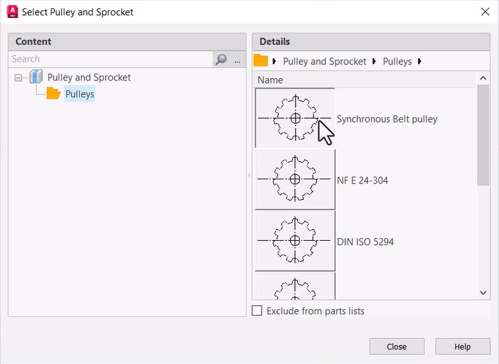
- In the Select Pulley and Sprocket dialog box, select Pulleys>Synchronous Belt pulley.
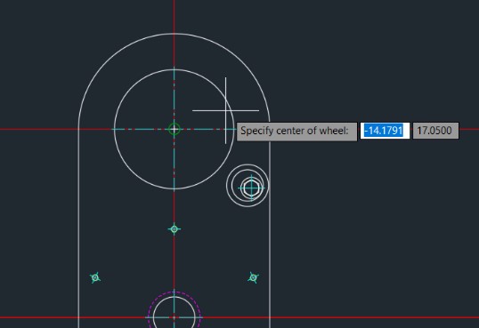
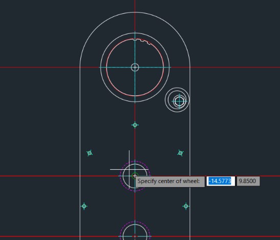
- To place the pulley in the drawing, at the Specify center of wheel prompt, select the center of the top circle, as shown below.
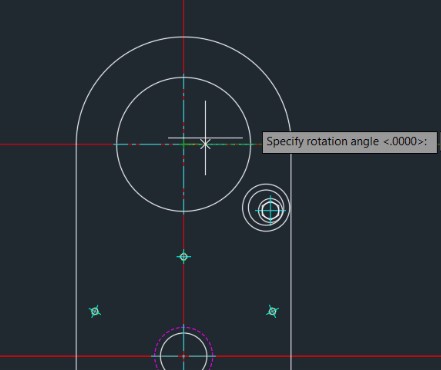
- At the Specify rotation angle prompt, press <Enter> to accept the default value of 0, as shown below.
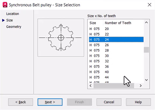
- In the Synchronous Belt pulley dialog box, on the Size tab, select H 075 24 from the Size x No. of teeth list and click Next.
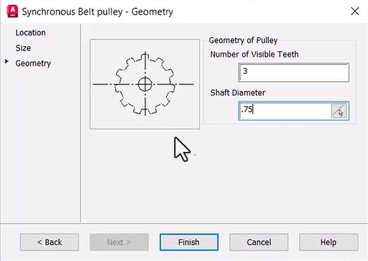
- On the Geometry tab, set the Number of Visible Teeth to 3 and the Shaft Diameter to .5, then click Finish.
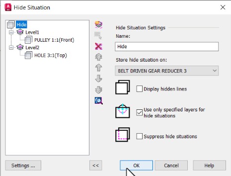
- In the Hide Situation dialog box, verify that Display hidden lines is unchecked, as shown below, and click OK.
- In the Content tab>Calculation panel, click the drop-down arrow next to Chains/Belts and select Sprocket/Pulley.
- In the Select Pulley and Sprocket dialog box, select Synchronous Belt pulley.
- To place the pulley in the drawing, at the Specify center of wheel prompt, select the center point of the circle of HOLE 5:1 of the FRONT view of the STAND, as shown below.
- At the Specify rotation angle prompt, accept the default value of 0.
- In the Synchronous Belt pulley dialog box, on the Size tab, select H 075 48 from the Size x No. of teeth list and click Next.
- On the Geometry tab, set the Number of Visible Teeth to 3 and the Shaft Diameter to .75, then click Finish.
- In the Hide Situation dialog box, verify that Display hidden lines is unchecked and click OK.
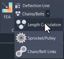
- In the Content tab>Calculation panel, click the drop-down arrow next to Chains/Belts and select Length Calculation.
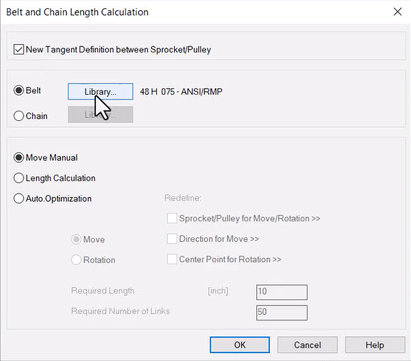
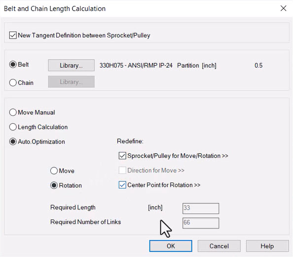
- In the Belt and Chain Length Calculation dialog box, ensure the New Tangent Definition between Sprocket/Pulley option is checked and the Belt option is selected, then click Library…
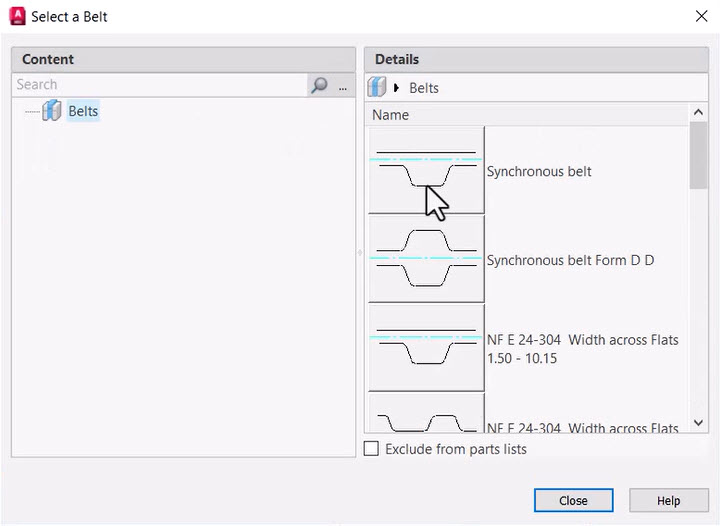
- In the Select a Belt dialog box, select Synchronous belt.
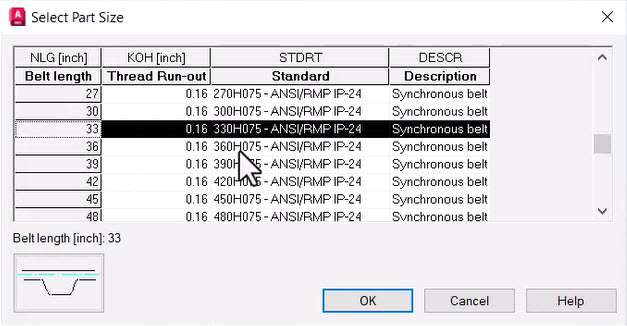
- In the Select Part Size dialog box, select the row with Belt length = 33, Thread Run-out = 0.16, Standard = 330H075 – ANSI/RMP IP-24, and Description = Synchronous belt (as shown below), and click OK.
- In the Belt and Chain Length Calculation dialog box, select Auto.Optimization and Rotation. Check the checkboxes for Sprocket/Pulley for Move/Rotation and Center Point for Rotation and click OK.
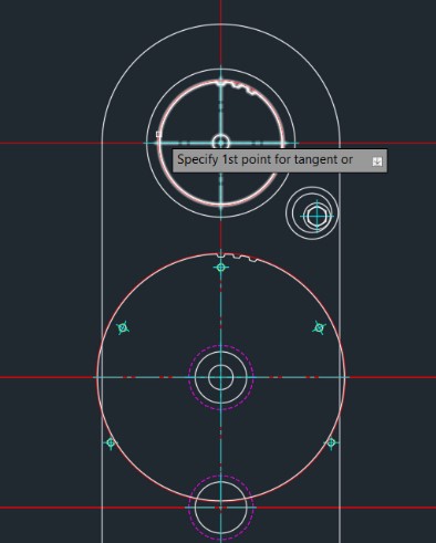
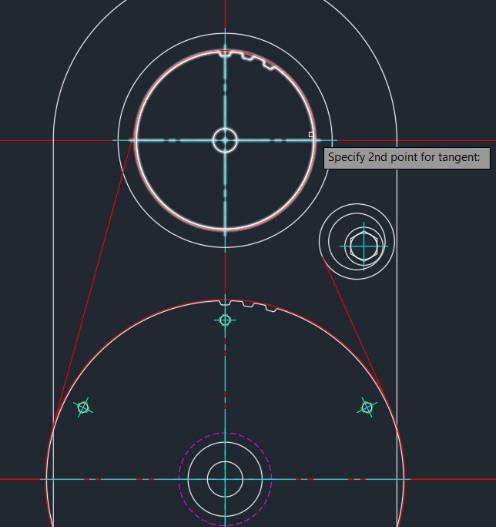
- For the first belt section, at the Specify 1st point for tangent prompt, select the upper-left quadrant of PULLEY 1:1 that you inserted earlier, as shown below.
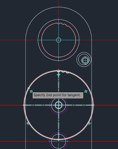
- For the first belt section, at the Specify 2nd point for tangent prompt, select the upper-left quadrant of PULLEY 2:1 that you inserted earlier, as shown below.
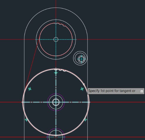
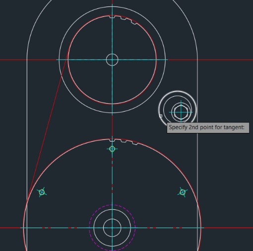
- For the second belt section, at the Specify 1st point for tangent prompt, select the upper-right quadrant of PULLEY 2:1, as shown below.
- For the second belt section, at the Specify 2nd point for tangent prompt, select the lower-left quadrant of the BELT DRIVE:1, as shown below.
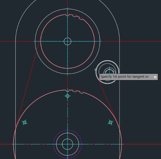
- For the third belt section, at the Specify 1st point for tangent prompt, select the upper-left quadrant of the BELT DRIVE:1, as shown below.
- For the third belt section, at the Specify 2nd point for tangent prompt, select the lower-left quadrant of the PULLEY 1:1, as shown below.
- With all three sections of the belt placed in the drawing, at the Specify 1st point for tangent prompt, right-click the mouse.
- At the Select pulleys or sprockets to be moved. Select objects prompt, select the two circles of BELT DRIVE:1, as shown below.
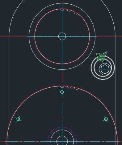
- To complete the task of selecting objects to be moved, right-click the mouse.
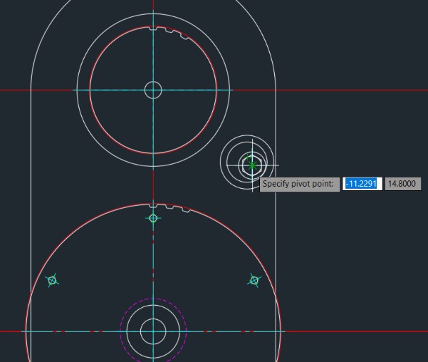
- At the Specify pivot point prompt, select the intersection of the two centerlines of HEX FLANGE SCREW – REGULAR THREAD – INCH 1:1, as shown below.
- If returned to the Belt and Chain Length Calculation dialog box, click Cancel to exit.
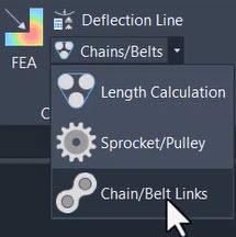
- In the Content tab>Calculation panel, click the drop-down arrow next to Chains/Belts and select Chain/Belt Links.
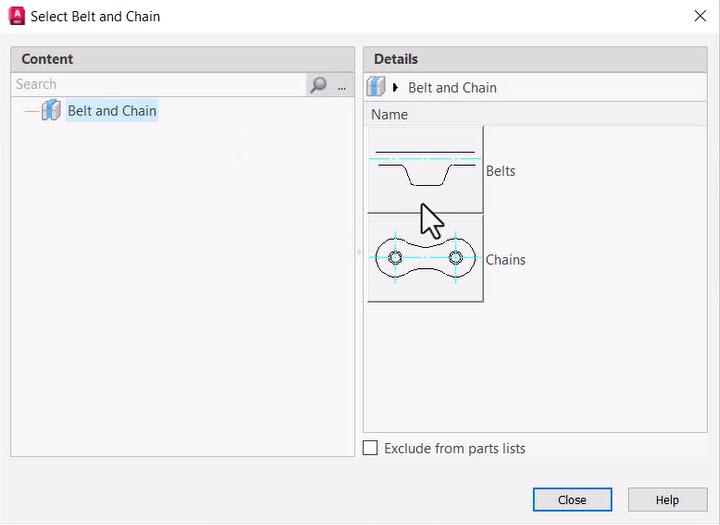
- In the Select Belt and Chain dialog box, select Belts.
- At the Select polyline prompt, select the top of the red polyline that represents the belt length that was just added, as shown below.
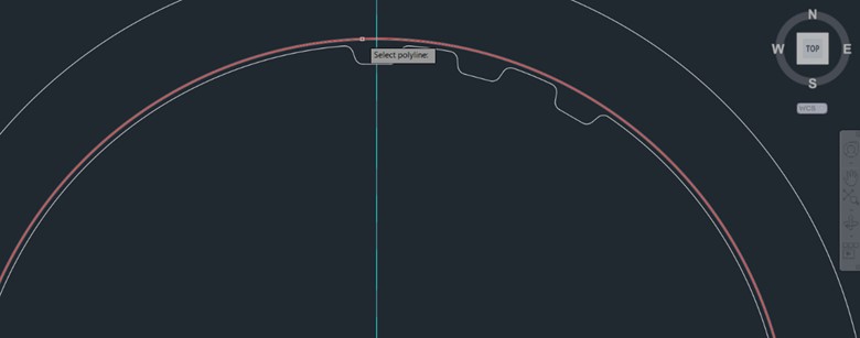
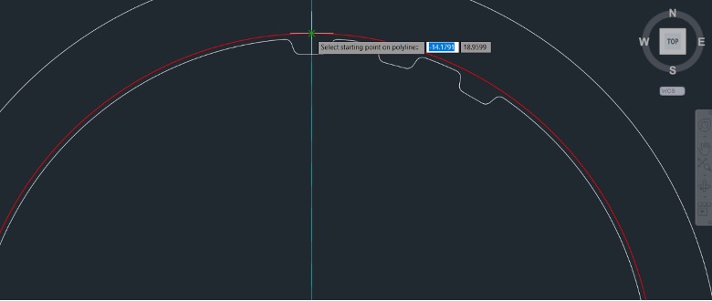
- At the Select starting point on polyline prompt, select the intersection of the top of the red polyline that represents the belt length and the vertical centerline, as shown below.
- In the BELTS dialog box, on the Size tab, ensure the 330H075 – ANSI/RMP IP-24 size is selected and click Next.
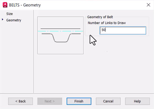
- On the Geometry tab, change the Number of Links to Draw to 50, then click Finish.
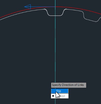
- At the Specify Direction of Links prompt, if the blue direction arrow is pointing to the left, choose the Flip option, as shown below.
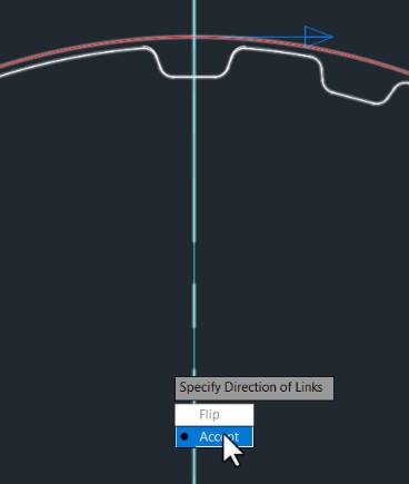
- At the Specify Direction of Links prompt, if the blue direction arrow is pointing to the right, choose the Accept option, as shown below.
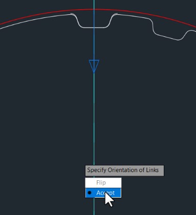
- At the Specify Orientation of Links prompt, and with the blue arrow pointing down, choose the Accept option, as shown in the image below.
- In the Hide Situation dialog box, verify that the Display hidden lines option is unchecked, then click OK.
- Save the drawing.